Baker BX Скачать руководство пользователя страница 15


Baker Band Resaw - Rev 1, 09/08; 

WWW.BAKER-ONLINE.COM


15  

Drive Wheel Adjustments 

The drive wheel’s position is set in the factory.  In most cases it never needs to be moved.  It 
can only be moved in and out, and should only be moved when the wheel is cocked so that 
the face cannot be lined up with the face of the idler wheel.  If you find that you must move 
this wheel, you will find a set screw located under the rubber dust cap, on top of the square 
tube, on the back side of the head rig, directly behind the wheel.  With this setscrew 
loosened, the wheel can be moved in or out, or removed completely.  If spindle and wheel 
assembly is moved, the spindle will need to be re-dimpled.  Retighten setscrew when 
finished. 

Note

It is important to re-dimple the spindle after moving or replacing it.


Idler Wheel Adjustments 

When looking at the front of the head rig, the idler wheel is on the left.  This wheel is used to 
adjust tracking problems.  Your tracking adjusters are located on the square tube on the 
backside of the head rig.  These two bolts make all of your tracking adjustments.  The bolt on 
the topside of the square tube is used for vertical adjustments.  The bolt on the backside of 
the square tube underneath the motor is used for horizontal adjustments.  Use these bolts to 
tilt the idler wheel so that it is lined up with the face of the drive wheel.  When the faces 
appear to be lined up, fine-tune it using the following procedure. 
 

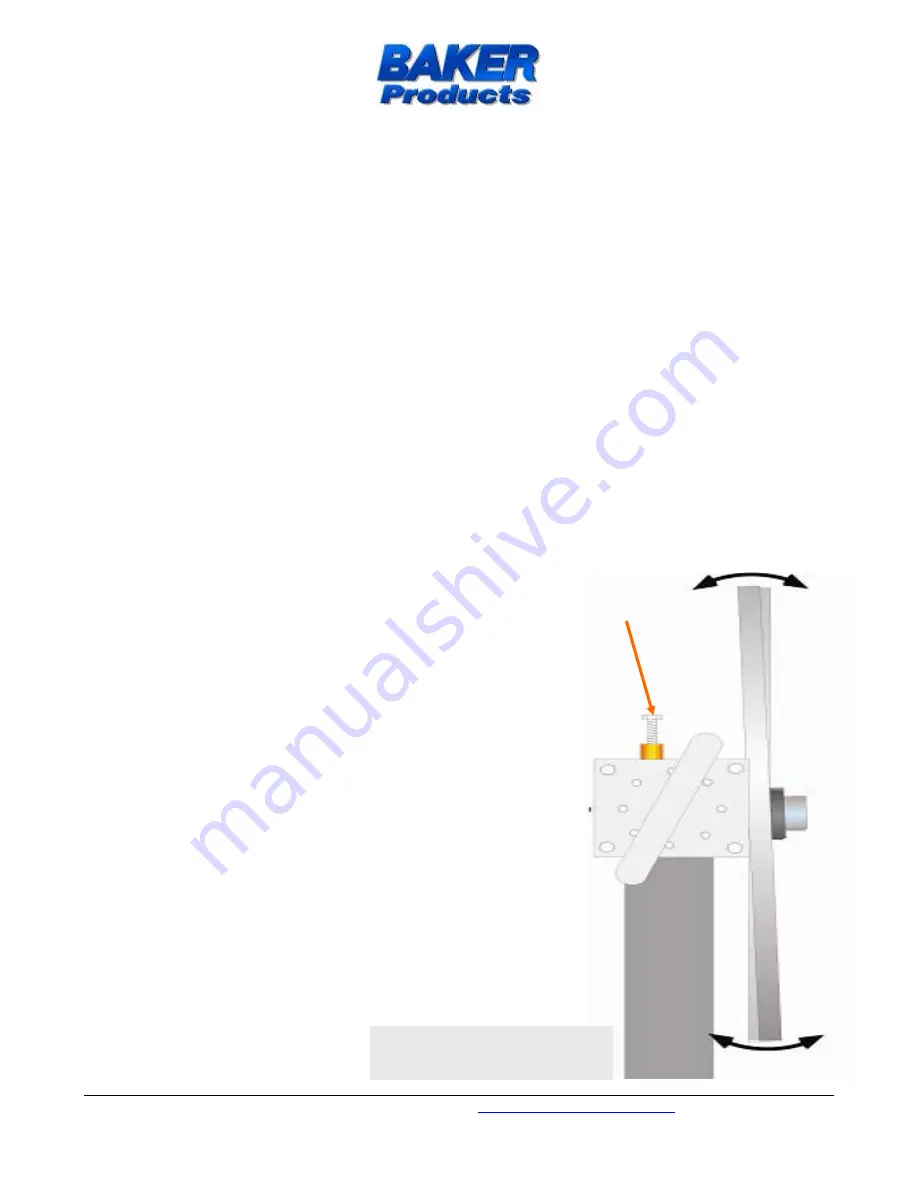
Vertical Adjustments 

  Rotate the wheel several rotations counterclockwise.  

Examine the positions of the back of the blade on the 
wheel at the top of the wheel and compare it to its 
position at the bottom of the wheel.  The blade position 
should be the same in both locations on both wheels.  If 
not, proceed to the next step. 

  If the blade needs to come forward at the top of the 

wheel, turn the vertical adjuster bolt clockwise.  If the 
blade needs to go back at the top of the wheel, loosen 
lock nut then turn the vertical adjuster bolt 
counterclockwise. 

  Manually turn the wheel several rotations and check the 

tracking as noted in the first step above.  If vertical 
tracking is still not correct, repeat the procedure until the 
blade position at the top and bottom of the wheel is the 
same (both idler and pull wheels). 

  Rotate the wheel several rotations clockwise and repeat 

the procedure, then tighten lock nut. 

Note:


When blade is tracking properly, the blade gullet 

should be flush with the front side of the wheels. 


Vertical 

Adjuster 

Bolt 

Figure C

: Vertical View 

with Covering Removed 

Содержание BX

Страница 1: ...Ba an nd d R Re es sa aw w U Us se er r M Ma an nu ua al l Ellington Industrial Supply Inc P O Box 128 Ellington Missouri 63638 USA Web site www baker online com E mail info baker online com Phone 57...

Страница 2: ...Power and Utilities Requirements 11 Operator Training 12 5 CHANGING BLADES 13 Removing Blade 13 Installing New Blade 13 Blade Tracking 14 Checking the Tracking 14 Drive Wheel Adjustments 15 Idler Whee...

Страница 3: ...e information contained in this manual FAILING TO DO SO MAY RESULT IN SERIOUS INJURY Machine Purpose The Baker B BX Band Resaw was designed to have a two point feed works allowing for running random w...

Страница 4: ...and blade used for the initial breakdown of a log Kerf The groove or thickness of the path cut by the saw teeth the total amount of sawdust removed during a single cut Lift Point A point where pressur...

Страница 5: ...machine must adhere to such regulations Machine Specifications and Requirements Power B 20HP TEFC BX 30HP TEFC Feedworks Conveyor Motor Driven by main engine Capacities B 6 x 12 6 wide conveyor BX 12...

Страница 6: ...ustrial Supply Inc does not warranty this machine to meet any other requirements or jurisdiction of any electrical or safety codes of any other state municipality other country or jurisdiction The pur...

Страница 7: ...ble for special indirect incidental or consequential damages however arising including but not limited to the loss of earnings or the cost of downtime Service Policy In the event that you have any pro...

Страница 8: ...IN MOVING PARTS ALWAYS WEAR SAFETY GLASSES AND HEARING PROTECTION AVOID KICK BACK BY KNOWING WHAT CONDITIONS CAN CREATE IT CHECK DAMAGED PARTS AND REPAIR OR REPLACE THEM IMMEDIATELY NEVER LEAVE MACHI...

Страница 9: ...e performing service or maintenance Energy Source Any source of electrical mechanical hydraulic pneumatic chemical thermal or other energy Lockout The placement of a lockout device such as a lock on a...

Страница 10: ...ant to highlight the unique and special features of the Baker B BX Band Resaw Footprint B Model single shown Adjustable Head Rig Powered Hold Down Blade Tensioning T handle Head Rig and Cowling Door C...

Страница 11: ...afety strap to avoid tip over Transport machine to the installation site Machine Positioning Placement Leveling Alignment For optimum performance designate a solid and level foundation that is covered...

Страница 12: ...of work Be sure personnel are properly trained and safety rules are clearly understood before operating or performing maintenance Operator Machine Guards Devices Instructions F FR RE EE E T TR RA AI...

Страница 13: ...hand Blade should be loose enough to be removed Push blade back and off of the right wheel Pull blade out of guides and remove If blade is not loose enough to remove from right wheel go back to the 3r...

Страница 14: ...ng appears to be correct after the above procedure your saw will cut without problems due to blade tracking However now rotate the idler wheel several rotations clockwise Check the blade in the same w...

Страница 15: ...bolt on the backside of the square tube underneath the motor is used for horizontal adjustments Use these bolts to tilt the idler wheel so that it is lined up with the face of the drive wheel When the...

Страница 16: ...to come forward turn the horizontal adjuster bolt counter clockwise Of course you ll need to loosen the lock nut first And don t forget to retighten the lock nut when finished adjusting Manually turn...

Страница 17: ...t of the blade and the other about 5 inches behind the blade Set the blade height to the thickness of the metal plates Use a straight edge to lie across the metal plates and over the blade Be sure the...

Страница 18: ...hem to adjust your front to back setting Side to Side Adjustments To cut quality lumber the blade must run parallel to the conveyor This is preset at the factory However if it ever gets knocked out yo...

Страница 19: ...e block as a reference set this surface at a right angle to the conveyor Use this to make sure the blade is running parallel to the conveyor When set properly lock down the Tilt Adjusters and retighte...

Страница 20: ...nhibiting the blades movement Eventually you will have to replace worn guide wheels and plates You should always keep spare guide wheels and plates on hand Under normal use guide plates should last ab...

Страница 21: ...find the best speed to run your wood types Hydraulics The Feedworks uses a hydraulic pump driven off of the main drive motor Dextron II Transmission fluid is recommended Conveyor Belts If the conveyor...

Страница 22: ...n place while it is being cut It can be placed closer to or further away from the blade by loosening the 2 front to back bolts on top of the hold down assembly Another 2 bolts on the front of the asse...

Страница 23: ...standard Baker BX uses the following blades 14 2 x 1 x 035 2T Woodmaster C Band Blades 14 2 x 1 x 035 also available NOTE 1 1 4 guide plates as well as other blade widths thickness and tooth spacing a...

Страница 24: ...lean with flammable or combustible materials Follow applicable codes and standards with regards to o Ventilation and monitoring of work area for excessive accumulation of hazardous vapors o Wearing pe...

Страница 25: ...be adjusting the head rigs See Cutting Angle Adjustment Boards that look like the image below are almost always problems with the blade A blade with more set on the top or with dull bottom teeth will...

Страница 26: ...QTY 2 per Head 111013 5VX710 Drive Belt QTY 2 101275 Bearing for 28 in Wheel 4 Bolt Hole QTY 1 per Head 171077 Spindle Nut N 11 QTY 1 181015 Hydraulic Pump If equipped w hyd Feedworks QTY 1 181019 Hyd...

Страница 27: ...Baker Band Resaw Rev 1 09 08 WWW BAKER ONLINE COM 27 Wiring Diagrams High Voltage...

Страница 28: ...Baker Band Resaw Rev 1 09 08 WWW BAKER ONLINE COM 28 Wiring Diagrams continued Low Voltage...

Отзывы: