ES-817 Rev. D
Copyright 2020. This document and all information herein are the property of Dresser LLC
Page 10 of 14
8
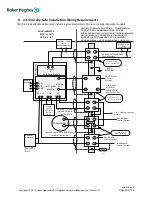
Intrinsically Safe Installation Wiring Requirements
Each intrinsically safe cable must include a grounded shield or be run in a separate metal conduit.
SV
I 3
Ho
u
sin
g
SVI3 Main Module
TRANSMITTER
+
-
NON-HAZARDOUS LOCATION - UNSPECIFIED
EXCEPT THAT BARRIERS MUST NOT BE
SUPPLIED FROM NOR CONTAIN UNDER NORMAL
OR ABNORMAL CONDITIONS A SOURCE OF
POTENTIAL WITH RESPECT TO EARTH IN
EXCESS OF 250 VOLTS RMS OR 250 VOLTS DC
HAZARDOUS
LOCATION
SEE 8.1, 8.2
SVI3 Options
Module
+
-
1
2
3
R
E
M
Remote
Mount
4-20 mA
OUT
SW 1 + 2
PV
1-5 VDC
OPTIONAL HAND
HELD
COMMUNICATOR
1
2
4
3
1
2
4
3
1
2
4
3
Optional
Field Load
SEE NOTE
8.3.2
Certified Active or
Passive IS Barrier
24 VDC from
Control System
1 to 5 Volts to Control
System
24 VDC from
Control System
Feedback to
Control System
Optional Intrinsically Safe Process
Variable Transmitter
LOAD
Optional 1-5 Volt
Process Variable
Input to SVI3
250
Equi-
Potential
SEE NOTE
8.3.2
DI
Simple
Passive
Apparatus
(Switch,
Relay)
1
2
4
3
Certified Active or
Passive IS Barrier
24 VDC from
Control
System
1 to 5 Volts
POSTION
FEEDBACK to
Control System
1
2
4
3
4-20 mA SETPOINT from
Control System
OPTIONAL HAND
HELD
COMMUNICATOR
4-20 mA
IN
+
-
Certified Active or
Passive IS Barrier
+
-
+
-
+
-


