16 | Baker Hughes
Copyright 2020 Baker Hughes Company. All rights reserved.
Warning:
Do not install operational trim and spray
nozzles until the pipelines have been completely
blown down and thoroughly cleaned. All debris must
be removed to protect the trim from damage.
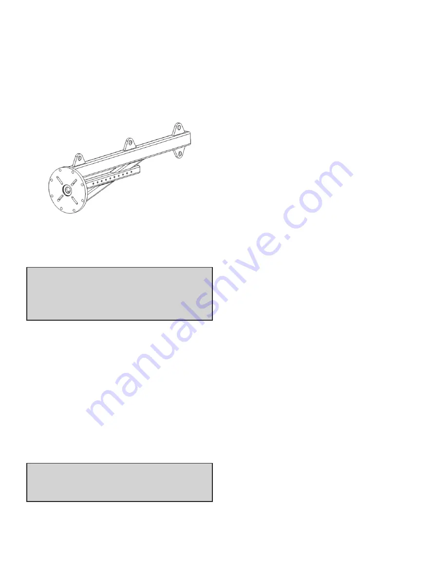
Trim Installation Device (TID)
A fixture to facilitate the safe and successful installation
or removal of trim from a valve body in the horizontal
orientation must be utilized. A local representative should
be contacted for information regarding the tool as trim-size
specific adaptors are required to mount the lifting tool.
For larger SteamForm valves installed in horizontal
orientation, special tool and care is required. Please
contact the Factory for recommendations.
Post Weld Heat Treatment and
Hydro-Testing
SteamForm valves are manufactured with either flanged
or butt weld end connections. For valves that require
welding into line, select welding rod that is compatible
with the valve connection material. Check the valve
specification sheet data for the body and end connection
material that is being supplied.
The applicable codes of the country or state of
installation specify welding and post weld heat treatment
requirements that must be followed. Verification of
localized welding temperatures by thermocouples is
advised.
Hydro-testing procedures can require a factory designed
test fixture, depending on whether or not the SteamForm
is used as a material or pressure class break point. In
this type of installation, isolation of the inlet section from
the outlet section is necessary to test each component
individually against its unique code required testing
conditions.
SteamForm Assembly
The SteamForm must be installed in line so the flow
through the valve follows the direction indicated on by the
flow arrow on the valve body.
After the steam lines are thoroughly cleaned and
hydrotested, it is safe to install the operating trim. For
start-up assistance from a certified technician, please
contact your local Baker Hughes Masoneilan sales office
or factory. For the complete installation procedure, please
refer to the SteamForm instruction manual.
Commissioning Spares
A full set of commissioning spares should be available on
site at all times to minimize the amount of downtime for
the SteamForm. Commissioning spares must include, at
a minimum, a full set of gaskets and packing to provide
the required soft-parts for reassembly.
Soft-parts such as gaskets and packing should never
be reused once they are removed from a valve. Do not
interchange components with parts supplied for other
valves.
Contact your regional Baker Hughes Sales office,
Aftermarket center or Channel Partner for spare parts
requests.
Turbine Bypass To Condenser
Applications
Several internal and external factors are introduced within
the turbine bypass applications, specifically in the bypass
to condenser application. The role of the SteamForm
becomes critical in ensuring equipment is protected
during the high pressure and temperature excursions.
Another major concern is for the limitation of noise as
high-energy steam is injected into a thin wall duct that
acts similar to a noise amplifier. These concerns are
addressed in more detail in the following sections.
Bypass System Requirements
The bypass to condenser design requires a significant
reduction in the heat level of the steam to reach an
enthalpy limit that is within the condenser design
limitations. Heat limits require the SteamForm to reduce
the steam temperature to the saturation range prior
to admission into the condenser. This application also
requires fast response to ensure safety valves remain
closed and prevent steam from venting outside of this
closed loop system.
Figure 13: Trim installation device
Warning:
Removing the operational trim during
these procedures is recommended to ensure the trim
is not damaged.


