4 | Baker Hughes
Copyright 2020 Baker Hughes Company. All rights reserved.
Installation
Three-way control valves are most commonly used on either
combining or diverting service. On combining service, the three-
way valve has two inlet ports and one outlet, and is used to
combine two fluids in variable proportions. On diverting service,
the three-way valve is used to split one inlet stream into two
outlets, or the incoming flow can be entirely diverted to one or
the other of the two outlet ports. As shown in the illustrations
opposite, these valves should be installed with flow tending to
open both ports. The principle advantage of this flow direction is
inherent stability.
Three-way valve ports are marked “C” for common, “L” for
lower and “U” for upper. Each of these letters is stamped on its
respective connection to facilitate correct installation.
Before placing the valve in the pipeline, clean the line thoroughly
of all dirt, welding chips, scale, oil or grease and other foreign
material. If valve connections are smaller than size of pipe,
swaged nipples or reducing fittings should be used rather than
bushings. If valve has a finned bonnet, do not insulate bonnet.
Air Piping
Pipe actuating air pressure line to the 1/4” NPT opening: in the
upper diaphragm case if an air-to-extend actuator (Type 37), in
the yoke if an air-to-retract actuator (Type 38). Use 1/4” O.D.
tubing or equivalent for all air lines. If air line exceeds 25 ft. in
length or if the valve is equipped with volume boosters, 3/8”
tubing is preferred. Air lines must not leak.
For valves equipped with 87/88 actuator, please refer to Manual
GEA19530B.
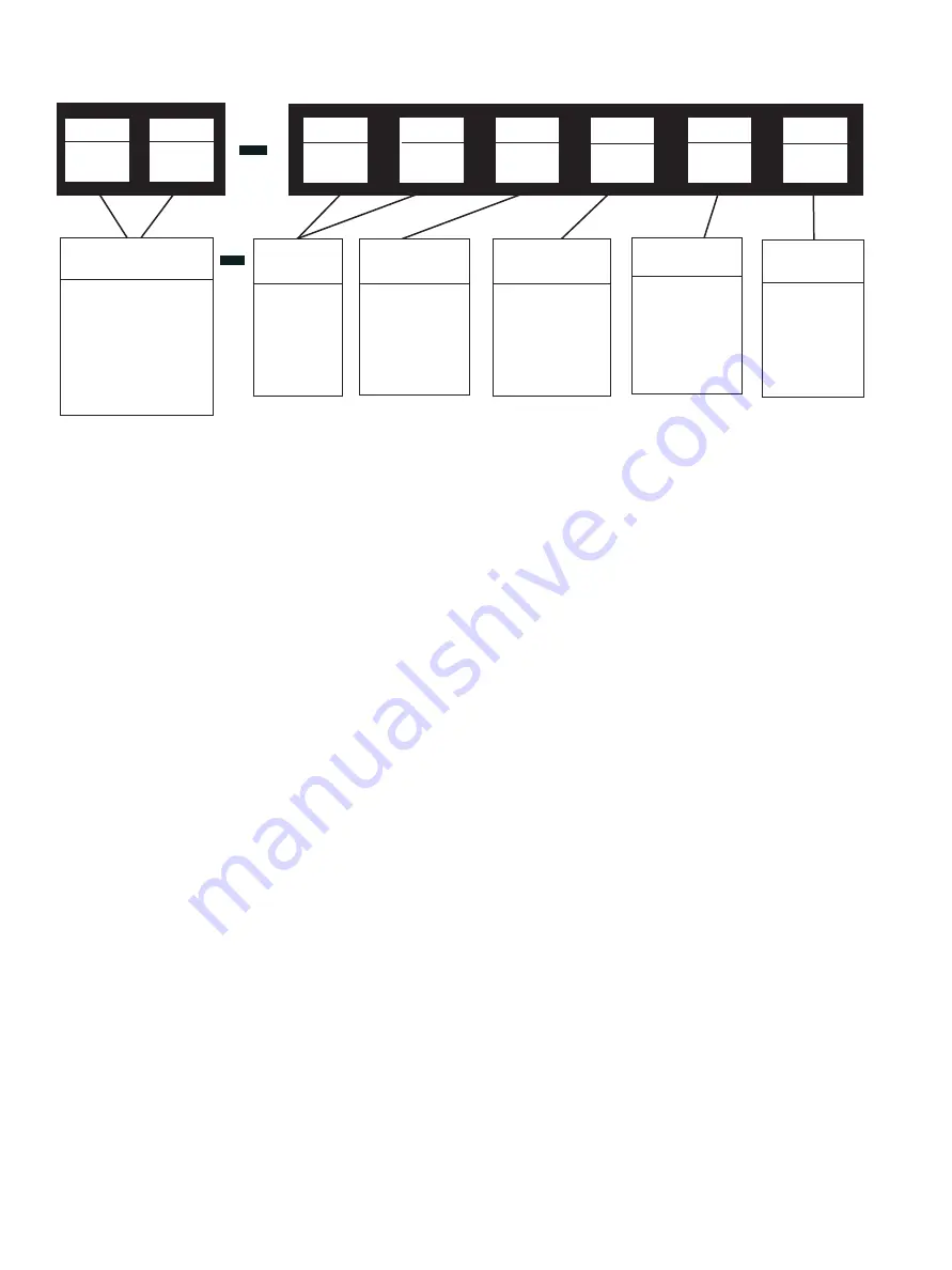
Numbering System
2nd
1st
8
5th
4th
8
3rd
3
2nd
0
1st
8
6th
3. Top and
Port Guided
Plug Type
Body
Series
80
Optional
Configuration
EB Extension
Bonnet
5. Combining
Design
6. Diverting
Design
Seat Type
Control
Characteristics
8. Linear
Ported
Actuator Type
(1)
87 Spring
DiaphragmDirect –
Air to close
88 Spring
DiaphragmReverse
– Air to open
Maintenance
Disassembly – 80385
1.
Apply sufficient air pressure to the actuator to position the
plug just off the upper seat (2).
2.
Remove nuts (48), bottom flange (7) and body gasket (49).
3. With smaller valves, loosen stem locknuts (27), turn them
down the plug stem (5) and lock them. With a wrench
applied over the locknuts, turn the plug stem (5) out of the
actuator stem. With larger valves, remove the split stem
connector (51).
4.
Unscrew drive nut (9) and remove actuator from the valve.
5. Remove locknuts (27) and travel indicator (58). Loosen
packing flange nuts (13) and turn plug stem down and out
of the packing box.
6. Remove plug from the valve body. Examine plug and seat
rings for wear and grind the seating surfaces (see Pages 5
and 6) if necessary.
7.
Remove nuts (48), bonnet (8) and gasket (49) from the
valve body.
8.
Remove old packing (14) with lantern ring (16) from the top
of the bonnet.
9.
Threaded seat rings are set up tightly when assembled
and are usually in service for years before replacement, so
that it is often difficult to remove them. To facilitate removal,
fabricate a special seat ring wrench to engage the seat ring
lugs and attach it to a shock wrench. If rings are exceptionally
stubborn, the application of heat or penetrating oil may
assist in removal.
(1) For valve with travel > 2.5”, actuator model 37/38 should be used.


