I-E96-416B
1 - 1
SECTION 1 - INTRODUCTION
OVERVIEW
The NTAI05 Analog Input Termination Unit inputs 15 or 16
channels of analog signals depending on slave module type. It
connects a slave module to field equipment and Bailey Controls
smart transmitters. The signals pass through slave modules to
the IMMFP01, IMMFP02 and IMMFP03 INFI 90 Multi-Function
Processors, IMAMM03 Analog Master Modules or NMFC03,
NMFC04 and NMFC05 Multi-Function Controllers.
This manual explains the purpose, setup, handling precau-
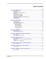
tions and steps to install the NTAI05 unit. Refer to the
Table of
Contents
to find the information needed. Refer to the
entry in this section to get started.
INTENDED USER
System engineers and technicians should read this manual
before installing and using the NTAI05 unit. Install and power
up the unit only after reading and understanding this manual.
TERMINATION UNIT DESCRIPTION
The NTAI05 unit is a single printed circuit board that mounts
to an NFTP01 Field Termination Panel. The termination unit
(TU) has one cable connector for signals. P1 carries the inputs
to the slave module through the cable. The terminal blocks for
field wiring are on the termination unit.
The dipshunts on the NTAI05 unit set the input type. Refer to
the appendix for the switch settings of the slave module used.
Be sure to check the switch setting before inserting the module
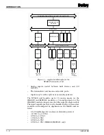
into the module mounting unit (MMU). Figure
shows an
example of the NTAI05 unit in a system.
FEATURES
The design of the NTAI05 unit, as with all INFI 90 devices,
allows for flexibility in creating a process management system.
Refer to the
entry of this section for the list
of devices that can be used with the termination unit in an
INFI 90 system.
•
A standard factory-wired cable connects the termination
unit to the slave module.
•
On-board terminal blocks accept field and I/O wiring.

