INSTALLATION
SELECTING OPTIONS
I-E96-117B
3 - 3
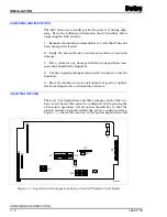
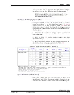
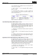
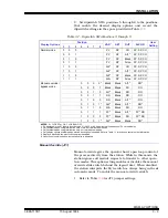
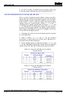
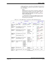
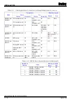
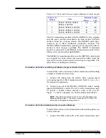
jumpers on the station circuit board. Tables
through
show the SAC station dipswitch and jumper settings.
Diagnostics (SW1, Position 1)
The diagnostics setting (dipswitch SW1, position one) is used
only by the factory. Check this dipswitch setting and verify that
it is in the correct position for normal operation. The SAC sta-
tion will not operate normally in the diagnostics setting. To
check this dipswitch setting:
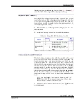
1. Refer to Table
for the dipswitch setting required for nor-
mal operation.
2. Verify that the dipswitch is set for normal operation.
Communication Rate (SW1, Position 2)
The SAC station communicates with the module in two baud
rates. The baud rate must match the module capability. The
baud rate determines how many stations can reside on one
serial link. Select the communication rate (five or 40 kilobaud)
for the RS-485 communication port that matches the commu-
nication rate of the module. The baud rate of the controller
module and MFC module are fixed at five kilobauds. The MFP
module needs to have specification S3 of function code 90 set
for the desired baud rate. The default baud rate is five kilo-
bauds. To select 40 kilobauds, add 100 to S3 of block 20, func-
tion code 90 (e.g., 100 or 101). To select the communication
rate:
NOTE: Only the IMMFP03 Multi-Function Processor Module or
IMMFP01 and IMMFP02 module with revision level C.0 or higher
firmware have 40-kilobaud communication rates.
1. Determine the communication rate for your application (5
or 40 kilobaud).
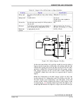
Table 3-1. Dipswitch SW1 Positions 1 and 2
Option
Position
Description
User
Setting
1
2
Diagnostics
1
Enable diagnostics. Do not use.
0
0
Normal operation.
Communication
rate
1
Enable 40 kbaud (>8 stations).
0
Enable 5 kbaud (8 stations max-
imum).
NOTES: 0 = CLOSED or ON, 1 = OPEN or OFF. Shaded area denotes default setting.


