INSTALLATION
DISPLAY OPTIONS
I-E96-117B
3 - 9
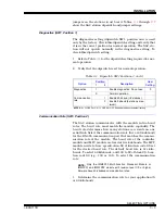
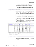
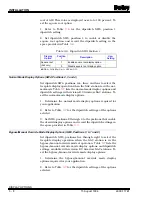
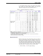
3. Set dipswitch SW4, positions 5 through 8 to the positions
that enable the desired display options and record the
dipswitch settings in the space provided in Table
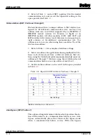
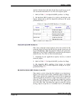
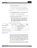
Manual Override (JP1)
Manual override gives the operator hard, open loop control of
the process directly from the station. While in this mode, the
station ignores all module requests to transfer to other opera-
tion modes. This option setting enables or disables the manual
override slide switch behind the legend door. When disabled,
the station interprets the M/A switch as always being in the
A
automatic mode. To enable the manual override switch:
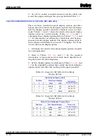
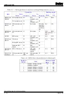
1. Refer to Table
for JP1 jumper settings.
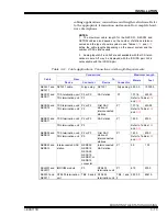
Table 3-7. Dipswitch SW4 Positions 2 through 8
Display Options
Position
VAR
1
SET
OUT
ALPHA
1
User
Setting
2
3
4
5
6
7
8
Normal mode
0
0
0
PV
SP
CO
PV, SP, CO
0
0
1
PV
SP
AI1
2
PV, SP, CO
0
1
0
PV
SP
Blank
PV, SP, CO
0
1
1
PV
SP
All on
PV, SP, CO
1
0
0
AI2
3
SP
CO
PV, SP, CO
1
0
1
AI2
3
SP
AI1
2
PV, SP, CO
1
1
0
AI2
3
SP
Blank
PV, SP, CO
1
1
1
AI2
3
SP
All on
PV, SP, CO
Manual override/
bypass mode
0
0
0
0
4
Blank
Blank
AI1
2
DO
5
0
0
0
1
Blank
Blank
DO
DO
0
0
1
0
AI1
2
Blank
DO
DO
0
0
1
1
DO
Blank
DO
DO
0
1
0
0
DO
Blank
AI1
2
DO
0
1
0
1
4
AI2
3
Blank
AI1
2
DO
5
0
1
1
0
AI2
3
Blank
DO
DO
0
1
1
1
PV
6
Blank
AI1
2
PV
6
, DO
1
0
0
0
PV
6
Blank
DO
PV
6
, DO
1
0
0
1
4
AI2
3
Blank
Blank
DO
5
NOTES: 0 = CLOSED or ON, 1 = OPEN or OFF.
1. PV displayed is the S1 input to function code 21, 22, 23 or 80. It applies to all indications of PV on the display.
2. Only available when using termination units or NIDS01 termination modules.
3. Only available when using termination units, not termination modules.
4. Only display options available when electric drive option is enabled. Refer to Table
for action on control output information.
5. Display is blanked when electric drive option is enabled.
6. Upon loss of communication, last known value is displayed.
15 August 1994
I-E96-117B1

