DESCRIPTION AND OPERATION
SAC STATION I/O CIRCUITRY
I-E96-117B
2 - 17
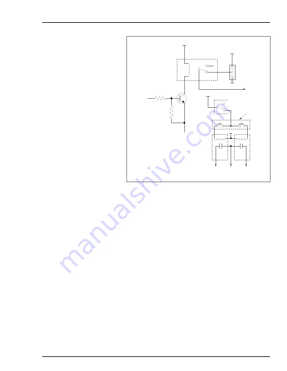
all the station's I/O circuits. Control signals (e.g., ELEC_DRV~)
are asserted to the proper state as defined by the user select-
able option dipswitches. If the electric drive option is enabled,
ELEC_DRV~ is asserted low, transistor Q1 is off and relay K1 is
de-energized. With K1 de-energized, pressing the raise/lower
membrane pushbutton causes the associated raise/lower relay
to energize closing the contact output, which jogs the electric
drive. If the option is disabled, ELEC_DRV~ will be asserted
high, causing Q1 to turn on and energizing relay K1. When K1
is energized, the M/A_SELECT signal goes to an open circuit
and the series circuit powered from the M/A_PWR and M/
A_COM inputs open. This disables the raise/lower contact
outputs.
When the SAC station exits electric drive bypass/manual over-
ride mode to normal mode operation, the new value for control
output will be the value of the analog input as defined in the
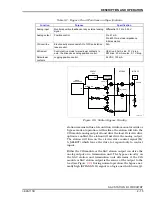
column of Tables
and
labeled action on control output.
At the time of transfer, either AI1 or AI2 will become the control
output value written to the CIS module. Normally, AI1 is the
position feedback from the device and AI2 is the process vari-
able. For more information on electric drive operation refer to
.
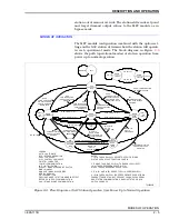
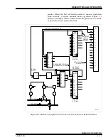
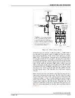
Figure 2-9. Electric Drive Circuit
ELEC_DRV ~
1 = NO EFFECT - Q1 IS ON AND K1 CAUSES N.O.
CONTACT CLOSURE AND MA SIGNAL FLOATS.
0 = Q1 IS OFF AND K1 IS OFF CAUSING N.C.
CONTACT CLOSURE. JP2 SETTING DETERMINES IF
MA_SELECT SIGNAL SOURCES OR SINKS +24 VDC.
NOTE: JP2 IS LABELED JP4 ON PC BOARD
WITH REVISION LEVEL 66308095A1.
I/O POWER SUPPLY
RELAY K1
RELAY K1
L
R
RAISE/LOWER
PUSHBUTTONS
LOCATED ON
FACEPLATE
Q1
ELEC_DRV ~
N.O.
N.C.
1
2
3
M/A_PWR
M/A_PWR
M/A_COM
M/A_COM
LOWER
R/L
COM
T00294A
RAISE
L
R
SELECT
JP2

