Contents of Figure
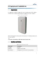
Figure 2-1 Appearance of CW0100 .............................................................................. 5
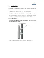
Figure 2-2 Install on pole A ........................................................................................... 7
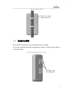
Figure 2-3 Install on pole B .......................................................................................... 8
Figure 2-4 Mounting Hole of Install on Wall ................................................................. 8
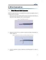
Figure 3-1 Strip Shielded Twisted Pair ......................................................................... 9
Figure 3-2 Separate the metal net, wire of cable and aluminum foil layer .................. 9
Figure 3-3 Cut off the aluminum foil layer of twisted pair ........................................... 10
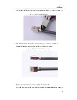
Figure 3-4 Color Order ............................................................................................... 10
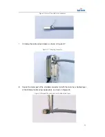
Figure 3-5 Insert the twisted pair core into line card .................................................. 10
Figure 3-6 Insert line card into Connector .................................................................. 11
Figure 3-7 Crimping connector ................................................................................... 11
Figure 3-8 Impact the connector with cable shield layer ............................................ 11
Figure 3-9 Cut off the redundant part ......................................................................... 12
Figure 3-10 Completion of shielded connector .......................................................... 12
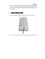
Figure 3-11 Connect Cable 1 ..................................................................................... 13
Figure 3-12 Connect Cable 2 ..................................................................................... 14
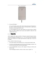
Figure 3-13 POE power Mode .................................................................................... 15


