


Page 28
Device manual
6490B / 6490B-y / 6590B
W. Bälz & Sohn GmbH & Co. Koepffstraße 5 D-74076 Heilbronn Telefon (07131) 1500-0 Telefax (07131) 1500-21
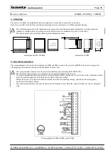
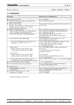
6. Commissioning
Procedure:
Remedy in case of malfunctions:
Unit properly installed ?
See 4. Mounting
Electrical connection according to valid regulations
and connection diagrams ?
See 5. Electrical connection
Switch on mains voltage.
When the unit is switched on, all display elements on the
front plate light up for approx. 2 sec. (lamp test).
Then the unit is ready for operation.
Compare operating voltage (indicated on the type plate) with
mains voltage
Switch over to manual mode.
See 2.2 Opening/closing the actuator in manual mode
Does the actual value display PV correspond to the
process variable at the measuring location ?
Check sensor, measuring line and electrical connection.
See 5. Electrical connection
Actual value display PV is fluctuating/jumping ?
Adjust measuring filter FIL. See 3.17 FIL
Unit installed close to powerful electric or magnetic
interference fields ?
Connecting and setting *digital inputs
Check settings of the digital inputs (see 3.21-3.25)
Check electrical connection (see 5.)
- Is the corresponding DI-state text displayed in the
SP-display (e.g. "StOP", "CLOS", ...) ?
Check voltage supply for digital inputs, external switching
contacts, signal lines and electrical connection.
Consider the display priorities like explained
in 2. Operating and setting.
Open actuator
See 2.2 Opening/closing the actuator in manual mode
- Heating controller: actual value PV rising ?
No response
- Cooling controller: actual value PV falling?
Check actuator and electrical connection
controller
↔
actuator
Close actuator
- Heating controller: actual value PV falling ?
reverse response
- Cooling controller: actual value PV rising ?
Change the actuator control OPEN and CLOSE
See 5.1 Wiring diagram
Is the bargraph rising while the actuator opens ? *
See 3.28 Y.SY, Y.SY; has to be 0...3 to activate the bargraph
- bargraph is not rising - all bargraph LEDs stay dark ?
Enter actuating time of connected actuator
See 3.6 Actuating time t.P
Set controller parameters using optimisation
See 3.1 Optimisation for automatic determination of
favourable control parameters OPt
Automatic mode
Manual/automatic switch over
See 2.2 Opening/closing the actuator in manual mode
Set setpoint SP
See 2.1 Setting setpoint in automatic mode
Controller actuating pulses are too short,
Adjust dead band db
switching rate is too high ?
See 3.5 dead band
* Option / depending on type of device


