Page A5/9
Operating Instructions
BA 7020
Technical specifications subject to change without notice
Copyright according to ISO 16016
BA_7020_00_EN_MJ_4917
A4. MENU ITEMS
A4.1 IMM menu
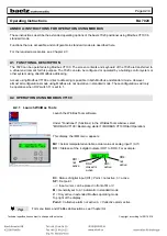
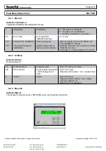
Indication Main with Manual operation:
Actual value, setpoint, statuses of digital outputs and inputs, manual/automatic operation.
Abbreviation Written out
Parameter/Function
Explanation
MV
Manipulated
Variable
Manipulated variable,
actual value AI1
0%–100% or
E = Error from sensor break at analog input 1
SP
SetPoint
Setpoint
0%–100% or
E = Error from sensor break
I = Initialization in progress
S = Stopped, i.e. uninitialized
DO
Digital Outputs Digital outputs
DO1: Point = Not active, ↑ = Up is active
DO2: Point = Not active, ↓ = Down is active
DO3: Point = Not active, 3 = DO3 is active
DO4: Point = Not active, 4 = DO4 is active
DI
Digital Input
Digital input
DI1: Point = Not active, 1 = DI1 is active
A
Alarm
Collective alarm
(see also IA menu)
Point = Not active, A = Collective alarm active
→
Input cursor
Can be placed in front of M or V
M
Manual
Manual operation
Always set to A = Automatic in standard mode
V
Value
Numeric value manual
specification
Only active in extended Modbus operating mode
A4.2 IVS menu
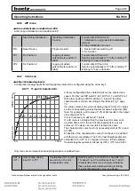
Indication Values and Switches:
Various (measured) values, DIP switch and hardware statuses.
Abbr. Written out
Parameter/Function
Explanation
AI1
AI2
AI3
AI4
SI2
SP
MO1
MO2
AO1
AO2
Analog Input 1
Analog Input 2
Analog Input 3
Analog Input 4
Scaled Analog Input 2
SetPoint
Modbus Analog Output 1
Modbus Analog Output 2
Analog Output 1
Analog Output 2
Analog Input 1 (AI1)
Analog Input 2 (AI2)
Analog Input 3 (AI3)
Analog Input 4 (AI4)
AI2, scaled
Setpoint
Modbus AO1
Modbus AO2
Analog Output 1 (AO1)
Analog Output 2 (AO2)
Arrow keys (↑↓) scroll from AI1, AI2 etc. to AO2.
Values for outputs or inputs are indicated,
otherwise:
E = Error from failure or no specification
S
(DIP) Switches
DIP switch position
1-9 and 0 (=10), 1 (=11), 2 (=12)
↓ = Switch set to 0, ↑ = Switch set to 1
HO
Hardware Outputs
Real hardware digital
output statuses
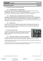
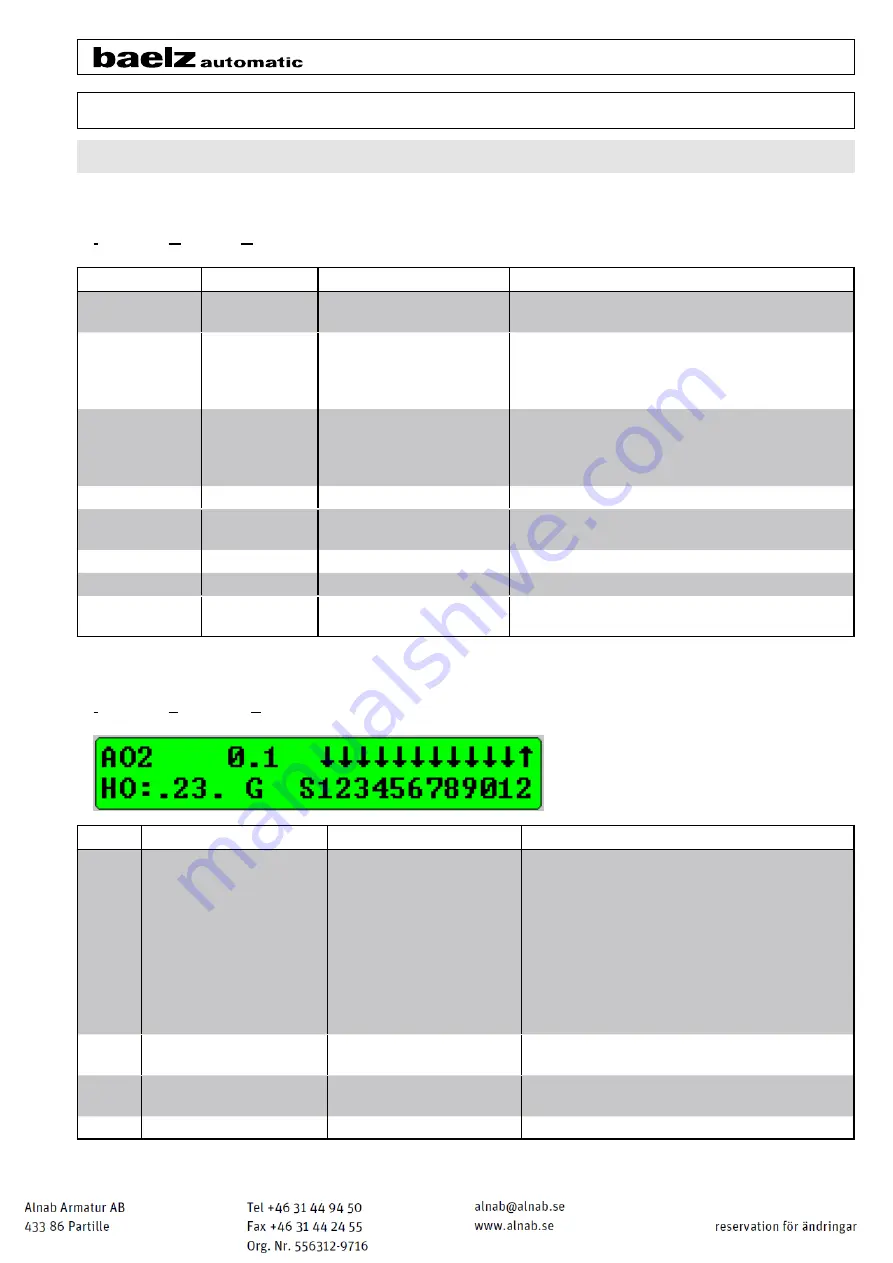
Example (see above figure): HO: .23.
= DO1 & DO4 not active, DO2 & DO3 active
GR
Green / Red (LEDs)
G = Green on, R = Red on If the LED is off, no letter is displayed


