


BA_375-E42_01_DEF_MJ_4419
21 |
32
W. Baelz & Sohn GmbH & Co.
· Koepffstrasse 5 · 74076 Heilbronn · Germany ·
www.baelz.de Seite | Page
Motorized Rotary Actuator
baelz 375-E42
7.4
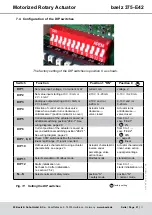
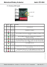
Configuration of the DIP switches
= factory setting
The factory setting of the DIP switches is position 0, as shown.
Fig. 11: Setting the DIP switches
Switch
Function
Position 1 "ON"
Position 0
DIP 1
Set value input: voltage, V or current, mA?
current, mA
voltage, V
DIP 2
Set value input starting at 0 V / 0 mA or
2 V / 4 mA?
2-10 V / 4-20 mA
0-10 V / 0-20 mA
DIP 3
Analogue output starting at 0 V / 0mA or
2 V / 4 mA?
2-10 V and / or
4-20 mA
0-10 V and / or
0-20 mA
DIP 4
Direction of control action: does valve
close when actuator turns clockwise or
anticlockwise? (position indicator in cover)
Actuator turns
clockwise →
valve closed
Actuator turns
anticlockwise →
valve closed
DIP 5
Current position of the actuator is saved as
additional switching position "2EZ-1". See
from 0 to 1 →
save "2EZ-1"
= 2%
DIP 6
Current position of the actuator is saved as
second additional switching position "2EZ-1".
from 0 to 1 →
save "2EZ-2"
= 98%
DIP 7, 8, 9
These 3 DIP switches define the function:
linear / split range / 11-point / inverted
s. , page 24
= linear
DIP 10
Defines valve characteristic using actuator
Actuator characteristic
inverse equal
percentage, valve
action linear
Actuator characteristic
linear, valve action
equal percentage
DIP 11
Selects standard or Modbus mode.
Modbus mode
standard mode
DIP 12
Starts initialization run.
Set back to 0 after initialization
from 0 to 1 →
starts initialization run
N↔S
Selects normal or safety mode
position "S"
= safety mode
position "N"
= normal mode