


24 |
32
W. Baelz & Sohn GmbH & Co.
· Koepffstrasse 5 · 74076 Heilbronn · Germany ·
www.baelz.de Seite | Page
Motorized Rotary Actuator
baelz 375-E42
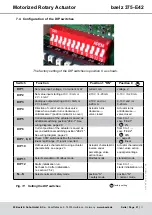
7.5 Commissioning
7.5.1 Quick start guide
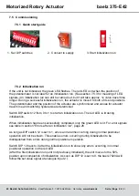
1. Set DIP switches
2. Connect to supply
3. Start initialization run
7.5.2 Initialization run
If the unit is not initialized, the green LED flashes. The red LED is lit when the position of
the potentiometer is not ideal for an initialization run. (See section
signals.) An initialization run can still be carried out, but it will take approx. 1x valve travel time
longer. During a successful initialization run, the actuator is moved to both of its end positions.
The potentiometer and the position of the actuator are synchronized and values for actuator
travel time and switching hysteresis are determined.
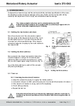
Switch DIP switch 12 from 0 to 1 to start an initialization run. The red LED is lit during
initialization.
When initialization has been successfully completed, only the green LED is lit. For error signals
see table in section "Errors after an initilization run", page 26
As long as DIP switch 12 is set to 1, errors and alarms occurring during normal positioner
operation will not be shown. This enables errors occurring during initialization to be
distinguished from errors during normal positioner operation.
Switch DIP 12 back to 0 after the initialization run to show any errors occurring in normal
positioner operation on the red LED.
(After the first initialization run (unit not previously initialized), the unit moves to the 50%
position upon completion of initialization. As soon as DIP 12 is set to 0, the baelz 7020A will
follow the set value signal at analogue input 2.)
LED
signal
LED
signal
Meaning
1
green off
red off
Unit is switched off.
2
green off
red on
Initialization run in progress.
3
green
flashing
red off
Unit is not initialized. Potentiometer in ideal position for initialization run (between 7.5 and
17.5%).
4
green
flashing
red on
Unit is not initialized. Potentiometer not in ideal position for initialization run.
Initialization still possible.
(If the red LED is flickering, the position of the potentiometer is at the edge of the optimal range and therefore OK.)
5
green
and red
flashing
Error during initialization. Unit is not initialized. The flashing red LED shows the number
of the error code: 3 flashes, interval, 3 flashes, interval → error code 3. See also section
.
6
green on
red off
Unit is initialized. No errors.
7
green on
red on
Immediately after the unit is switched on, both LEDs are lit for 2 seconds to show that they
are in working order.
8
green on
red
flashing
Unit is initialized. DIP 12 set to 1 → error after initialization run, see section
DIP 12 set to 0 → error or alarm during normal positioner operation, see section
.
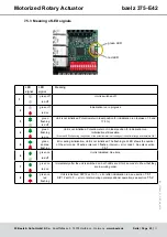
12
↑
0
1