


20 |
32
W. Baelz & Sohn GmbH & Co.
· Koepffstrasse 5 · 74076 Heilbronn · Germany ·
www.baelz.de Seite | Page
Motorized Rotary Actuator
baelz 375-E42
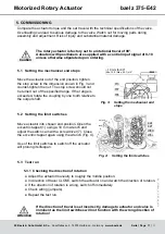
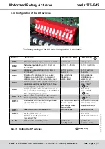
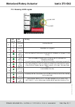
Fig. 10: Wiring diagram with digital positioner baelz 7020A
7.3.2 Allocation of connection terminals
Terminal
Allocation
Notes
2, 3
supply terminals
See wiring diagram for
correct allocation.
4, 5, 12, 14
Can be allocated to an
overriding external control
system (freeze protection,
excessive temperatures).
For external control, the
N↔S switch must be set
to „S“ (safety mode).
20, 22
Digital input for a switch
used to select between two
conditions,
e.g. „open / closed“ or
„summer / winter“.
23, 24, 25,
26
Analogue output position
indicater using voltage and
/ or current.
Analogue outputs
can be connected
simultaneously.
38, 39, 40
Connection terminals for
Modbus
91, 92, 93
Connection terminals for
potentiometer
U, 0, I
Input setpoint value for
valve position
IMPORTANT! Position of
DIP switch 1, see section
E1, E2, E3,
E4, E5, E6
Terminals for 2 digital
outputs
IMPORTANT! Position of
DIP switches 5 & 6, see
section 7.4
97, 98, 99
Connection terminals for
motor
Ex-works wiring varies
according to type of
actuator


