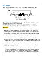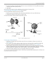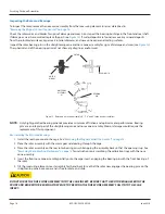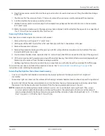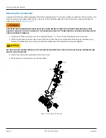
◊ Do not install check valves or pressure reducing devices upstream of the meter
◊ Valves immediately upstream of the meter should only be fully-open gate valves Butterfly valves are acceptable if they
are 5 pipe diameters or more upstream from the meter Downstream, fully open gate or butterfly valves can be used
◊ Unweighted check valves should not be located closer than 3 pipe diameters downstream of the meter
◊ Externally weighted check valves and pressure reducing devices should not be located closer than 5 pipe diameters of
the meter
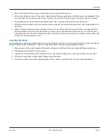
◊ When installing a compound meter and plate strainer of a size smaller than the pipe installation, to reduce the effect
of jetting caused by the increase in flow velocity, a minimum of 5 pipe diameters of pipe equal in size to the meter, is
required upstream of the meter Additional length is required if a sharp contraction or an eccentric reducer, rather than
a concentric, tapered reducer is used
Installing the Meter
Overall dimensions and laying lengths of each meter size are listed in the
Recordall Compound Series Meter Product Data Sheet
Review the dimensional requirements, choose an installation point in the piping, and proceed as follows:
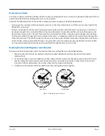
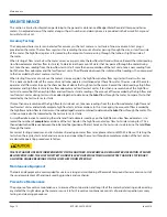
1 Measure precisely the overall length of the meter with gaskets attached to the inlet and outlet flange connections
2 Provide proper gap length in service piping
3 Install meter in the pipeline so that the flow arrow on the meter housing points in the same direction as water flow
4 With meter and gaskets in place, tighten flange connection bolts
5 To relieve possible strain on the piping, position a meter support under the meter housing where appropriate
Installation
June 2016
RCS-UM-00076-EN-04
Page 7

