background image

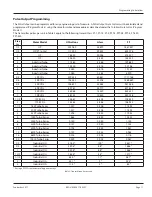
Pulse Output Programming

The 

Pulse Output

 can be programmed for any engineering unit of measure . A 

Pulse Output Scale Factor

 must be calculated and 

programmed (

Program Mode  6

) using the same formula and procedure as described under the 

Totalizer Scale Factor

 (

Program 

Mode 1

) .

The transmitter pulses per unit in Table 3 apply to the following transmitters: FT-1, FT-1E, FT-2, PFT-2, PFT-2E, PFT-3, FT-420, 

PFT-420

Size 

in.

Meter Model

US Gallons

Liters

Ft

3

1/2

OP

222 .960

58 .899

1687 .857

1/2

OP (FT1 only)

111 .500

29 .455

834 .078

1

OP

76 .640

20 .246

573 .307

2

OP

20 .600

5 .442

154 .099

2

Industrial Turbo

17 .360

4 .586

129 .862

3

Industrial Turbo

12 .400

3 .276

92 .758

4

Industrial Turbo

2 .560

0 .676

19 .150

6

Industrial Turbo

1 .080

0 .285

8 .079

5/8

LP RCDL

229 .554

60 .641

1717 .186

5/8

25 RCDL

198 .340

52 .396

1484 .689

3/4

35 RCDL

126 .671

33 .463

947 .566

1

40 RCDL

89 .781

23 .717

671 .610

1

55 RCDL

58 .064

15 .339

434 .351

1

70 RCDL

46 .752

12 .350

349 .726

1-1/2

120 RCDL

23 .867

6 .305

178 .539

2

170 RCDL

14 .565

3 .848

108 .955

1-1/2

160 Turbo Series

1 .537

0 .406

11 .495

2

200 Turbo Series

1 .537

0 .406

11 .495

3

450 Turbo Series

1 .598

0 .422

11 .955

4

1000 Turbo Series

1 .665

0 .440

12 .455

6

2000 Turbo Series

0 .150

0 .040

1 .122

8

3500 Turbo Series

0 .151

0 .040

1 .133

10

5500 Turbo Series

0 .198

0 .052

1 .481

12

6200 Turbo Series

0 .129

0 .034

0 .963

16

6600 Turbo Series

0 .016

0 .004

0 .116

20

10000 Turbo Series

0 .009

0 .002

0 .067

1/2

Industrial OG

378 .5 *

100 *

2831 *

3/4

Industrial OG

249 .8 *

66 *

1868 *

1

Industrial OG

249 .8 *

66 *

1868 *

1 HF

Industrial OG

162 .8 *

43 *

1217 *

1-1/2

Industrial OG

64 .4 *

17 *

481 *

2

Industrial OG

34 .1 *

9 *

255 *

3

Industrial OG

11 .4 *

3 *

85 *

* If using a PFT-3E transmitter, multiply number by 2 .

Table 3: Transmitter pulses per unit

Programming Calculations

Page 11 

September 2017

REG-UM-00471-EN-07

Содержание ER-10

Страница 1: ...Resettable Totalizer and Rate of Flow Indicator REG UM 00471 EN 07 September 2017 User Manual This product contains Lithium batteries Read this manual before attempting any installation wiring or ope...

Страница 2: ...Industrial Registers Models ER 10 ER 10 R ER 10H Digital Resettable Totalizer and Rate of Flow Indicator Page ii September 2017 REG UM 00471 EN 07...

Страница 3: ...rminals 7 Transmitter Connections 7 Operation 8 Display Types 8 Control Keys 8 Programming 9 Programming Calculations 10 Totalizer Programming 10 Rate of Flow Programming 10 Pulse Output Programming 1...

Страница 4: ...Industrial Registers Models ER 10 ER 10 R ER 10H Digital Resettable Totalizer and Rate of Flow Indicator Page iv September 2017 REG UM 00471 EN 07...

Страница 5: ...mer Service 1 800 876 3837 PRODUCT DESCRIPTION The ER 10 ER 10 R and ER 10H are external or battery powered electronic registers that display rate of flow and total flow They have independent programm...

Страница 6: ...o meet NEMA 4X Mode select programming button Gasket installed Install mounting clip Figure 1 Panel installation Battery Installation Replacement The ER 10 ER 10 R ER 10H are powered by one 3V Lithium...

Страница 7: ...bers in parenthesis refer to the terminal numbers on the ER 10 Connect the wire coming from the transmitter to the corresponding terminal number for the ER Series Remote models Connecting to a generic...

Страница 8: ...Total Rate key during normal operation the ER 10 toggles the display between the Flow Total and the Flow Rate The letter R on the left of the screen indicates that the Flow Rate is being displayed Pro...

Страница 9: ...ecimal point to the new position 3 0000 Mode 3 Rate Scale Factor display shows the lowercase letter d on the right when it is time to enter the decimal point position for the rate scaler NOTE N This d...

Страница 10: ...ls hour Rate scale factor To determine the Rate Scale Factor Program Mode 4 use the following formula Rate Scale Factor Seconds Transmitter Pulses per Unit Decimal Factor where Seconds is the number o...

Страница 11: ...0 52 396 1484 689 3 4 35 RCDL 126 671 33 463 947 566 1 40 RCDL 89 781 23 717 671 610 1 55 RCDL 58 064 15 339 434 351 1 70 RCDL 46 752 12 350 349 726 1 1 2 120 RCDL 23 867 6 305 178 539 2 170 RCDL 14 5...

Страница 12: ...3 Transmitter defective 1 Check programming 2 Check connections 3 Repair or replace transmitter Cannot program Program enable jumper is not installed or is installed improperly Install jumper from Te...

Страница 13: ...tank or into a calibrated vessel 5 Determine the number of pulses per gallon by dividing the indicator reading by the number of gallons of fluid in the vessel Use this value for your calculations Exam...

Страница 14: ...the balance of the above steps to re assemble the unit Disc meter 1 Remove the front cover on the ER 10 unit and disconnect the sensor wiring 2 Loosen the side seal screw on the assembly adapter twist...

Страница 15: ...rogrammable Rate Indicator Digits 4 5 4 calculated 5 displayed with fixed zero in LSD Scaler range 0 001 9999 Decimal point 5 positions programmable Accuracy 0 2 Update time 0 7 seconds Zero time 10 s...

Страница 16: ...alupe Inn CP 01050 M xico DF M xico 52 55 5662 0882 Europe Eastern Europe Branch Office for Poland Latvia Lithuania Estonia Ukraine Belarus Badger Meter Europe ul Korfantego 6 44 193 Knur w Poland 48...

Отзывы: