background image

Batch Controller Model CB-30

Page 6 

April 2017

CTL-UM-01028-EN-03

Assembling the CB-30

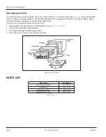
The CB-30 can be mounted on the flow meter, on a wall or shelf, or in an instrumentation panel  

Figure 2 

shows the exploded 

view of a meter or wall mounted unit  In this configuration the CB-30 is shipped separately and must be installed as shown 

(see wiring diagrams for proper transmitter signal connections) 
The basic unit is equipped for panel mount  To install:
1   Measure and cut mounting hole to the dimensions shown in 

Figure 1 on page 5


2   Install gasket around the mounting bezel 
3   Insert the unit through the front panel cutout 
4   Secure the unit to the panel with the mounting clips 

Figure 2:  CB-30 Assembly

PAOTS LIST

Description

Part Number

Mounting harware kit

259170-005

Connector kit

259170-004

Replacement triac

259170-003

Replacement face plate

259170-002

Table 1: Parts list

Содержание CB-30

Страница 1: ...CTL UM 01028 EN 03 April 2017 Batch Controller Model CB 30 User Manual...

Страница 2: ...Batch Controller Model CB 30 Page 2 April 2017 CTL UM 01028 EN 03...

Страница 3: ...30 7 Flow Valve Solenoid Connections 8 Pulse Transmitter Connections 9 Remote Control Connections 10 AC Power Supply Connections 11 Operating the CB 30 Front Panel 12 Setup Sequence 12 Function Keys 1...

Страница 4: ...Batch Controller Model CB 30 Page 4 April 2017 CTL UM 01028 EN 03...

Страница 5: ...put from the meter transmitter scales it to the desired unit of measure and at a preset point s sends a signal to operate the flow valve Other features include automatic compensation for valve overrun...

Страница 6: ...wiring diagrams for proper transmitter signal connections The basic unit is equipped for panel mount To install 1 Measure and cut mounting hole to the dimensions shown in Figure 1 on page 5 2 Install...

Страница 7: ...ircuit is recommended Do not bundle or route signal lines with power lines Keep all lines as short as possible Use shielded wire for all input wiring Observe all local electrical codes TO PREVENT ACCI...

Страница 8: ...will open and interrupt the AC supply to the solenoid therefore closing the valve The TRIAC is field replaceable TRIAC Rating SHARP S202T02F Load Voltage 80 240V AC Load Current 2 A Transistor Output...

Страница 9: ...the connection to Model PFT 3E transmitter usually supplied with a Badger Meter Industrial Turbo meter The Model PFT 3E provides an open collector transistor output for the CB 30 Frequency DC to 5 kH...

Страница 10: ...rom external noise interference Control Inputs Remote start reset hold manual keyboard lockout Frequency DC to 20 Hz typical Type Current sinking Logic Level sensitive Low Level 0 2V DC max High Level...

Страница 11: ...fuse for surge protection The unit is designed to operate with 85 265V AC power only Always make sure to connect terminal 23 to the electrical system ground AC Power Input 85 265V AC Consumption 0 VA...

Страница 12: ...start and reset the unit in addition to presetting the batch and allowing for manual operation Figure 7 Front Panel Setup Sequence The CB 30 is equipped with a programming lockout feature for critica...

Страница 13: ...the new value in memory Press and release the WASH 6 key to program the wash cycle amount of water up to 999 gallons Program zero if no wash cycle is needed Press and release the RESET key to reset a...

Страница 14: ...will count down from 30 gallons to zero but begin closing the valve at 5 gallons overrun and coast down to zero The indicator will then show BATCH READY again Stopping the Batch The operator can stop...

Страница 15: ...ple 5 This is the number that must be programmed to compensate for valve overrun 3 To program press COMP enter 5 then press ENTER The CB 30 will begin closing the valve 5 gallons prior to the Batch an...

Страница 16: ...s functioning properly The CB 30 is extensively tested at the factory before shipment However the unit may get damaged during transit or installation If after all possible remedies have been tried and...

Отзывы: