manualshive.com logo in svg
background image

16827

STOP!

STOP!

Call Us First!

DO NOT RETURN TO STORE.

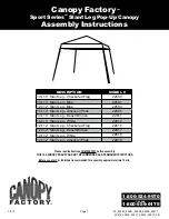
For immediate help with assembly or product information

call our toll free number:

1-800-844-9273

or email:

[email protected]

Our staff is ready to provide assistance

April through October M-F 8:00 AM to 4:30 PM EST

Saturday 8:30 AM to 4:30 PM EST

November through March M - F 8:00 AM to 5:00 PM EST

Содержание Yardline BELLINGHAM GABLE 10' x 16'

Страница 1: ...embly or product information call our toll free number 1 800 844 9273 or email customerservice yardline net Our staff is ready to provide assistance April through October M F 8 00 AM to 4 30 PM EST Sa...

Страница 2: ...This page intentionally left blank...

Страница 3: ...ilding ENGINEERED DRAWINGS Contact our Customer Service Team if engineered drawings are needed to pull local permits SURFACE PREPARATION To ensure proper assembly you must build your shed on a level s...

Страница 4: ...on Level Gloves Framing lumber is graded for structural strength and not appearance Exterior trim is graded for one good side Always install the material leaving the best edge and best surface visible...

Страница 5: ...hown below as shaded Below is a list of additional materials not included x3 x12 2 x 4 x 10 5 x 10 x 304 8 cm Treated Lumber Cut to 3 2 x 4 x 117 5 x 10 x 297 2 cm ea 3 7 6 cm Hot Dipped Galvanized Na...

Страница 6: ...5 1 x 10 2 x 243 8 cm TP 3 4 1 9 cm 1 x 3 x 5 2 5 x 7 6 x 12 7 cm Gauge Block for 3 4 1 9 cm measurement x1 GAA DOOR OO x2 1 1 2 x 2 1 2 x 69 3 8 x 6 3 x 175 3 cm 4 x14 6 x 24 15 2 x 61 cm OSB OR WOO...

Страница 7: ...IST x10 3 8 x 48 x 84 1 x 121 9 x 213 4 cm x1 RIGHT DOOR x1 LEFT DOOR x1 3 8 x 48 x 84 1 x 121 9 x 213 4 cm x1 3 8 x 48 x 84 1 x 121 9 x 213 4 cm x2 x2 x2 2 x 4 x 24 5 1 x 10 2 x 61 cm RL x5 x1 7 16 x...

Страница 8: ...cm 2 5 1 cm 1 1 2 3 8 cm x2 10 1 2 x 32 1 2 26 7 x 82 6 cm 1 2 5 cm x2 x1 64 Metal Threshold 3 4 1 9 cm x11 Bagged seperately special coating x16 1 2 5 cm x4 x1 x4 3 4 Tech Screw with drill point 1 1...

Страница 9: ...ding your shed on a concrete foundation see the following page CONCRETE MATERIAL REQUIRED x3 4 x 4 x 16 10 x 10 x 488 cm Treated Lumber Fasteners for Frame to 4 x 4 3 Screws shown as one option Minimu...

Страница 10: ...l sill plates Fasten 2 x 4 5 1 x 10 2 cm sill plates to slab using approved concrete anchors fasteners not included Check local code for concrete foundation requirements NOTES Allow new concrete slabs...

Страница 11: ...sure and mark BEGIN You have finished your floor frame Proceed to level and square frame FINISH 3 Flush Flush You will need to cut 2 x 4 x 120 boards down to 117 x2 2 x 4 x 192 5 1 x 10 2 x 487 7 cm L...

Страница 12: ...ill be approximately 226 7 16 575 2 cm When the frame is level and square secure one side of frame to the 4x4 runners using one fastener at ends of each runner Move to the opposite end of the frame Se...

Страница 13: ...quaring frame Fig C Check the floor frame is square by measuring diagonally across the frame corners If the measurements are the same your floor frame is square The measurement will be approximately 2...

Страница 14: ...part inside panels 5 7 6 x2 5 8 x 48 x 96 1 6 x 122 x 243 8 cm x2 5 8 x 47 7 8 x 48 1 6 x 121 9 x 122 cm x2 5 8 x 23 7 8 x 96 1 6 x 60 6 x 243 8 cm x238 2 5 1 cm FLOOR PANELS Grid lines up 5 8 x 48 x...

Страница 15: ...EAVE SIDE WALL Check the floor frame is level after installing floor panels Re level if needed HINT IMPORTANT The floor should be used as a stable work surface for wall construction Organize your ass...

Страница 16: ...at both ends for squareness BEGIN 1 Secure one PVA flush to the floor deck using two 3 screws Measure over 120 3 4 and install a second PVA flush to the floor deck PVA will overhang the floor Secure...

Страница 17: ...attach a second gusset using glue and 12 2 nails No need to use jig for this gusset 4 5 3 2 Keep ECN firm against outside PVA s as shown Fig A and push rafters tight to the middle PVA Rafters should...

Страница 18: ...OUR WALLS OPTIONAL DOOR LOCATED ON EAVE SIDE WALL toward right EAVE SIDE WALL WITH DOOR RIGHT IF YOU CHOOSE TO LOCATE THE DOOR TOWARD THE RIGHT GO TO Page 21 TO BEGIN BUILDING YOUR WALLS OPTIONAL DOOR...

Страница 19: ...ALL WITH DOOR x2 2 x 4 x 32 1 2 5 1 x 10 2 x 82 5 cm QS 32 1 2 82 5 cm 32 1 2 82 5 cm BEGIN 1 Use two 3 nails at each mark Orient parts on edge on floor Measure and mark 2 Maintain 67 dimension 104 1...

Страница 20: ...2 x 4 x 68 1 2 5 x 10 2 x 174 cm YFA 18 HINT For easier nailing stand on frame 3 7 6 cm PARTS REQUIRED x32 GABLE END WALL WITH DOOR 3 Orient parts on edge Use two 3 nails at each location AM YFA YFA...

Страница 21: ...e up as shown Secure panel with two 2 nails 6 15 2 cm apart Repeat Step 4 to attach the right 48 x 84 panel 5 4 48 x 84 121 9 x 213 4 cm x1 LEFT 1 RIGHT Maintain Flush Maintain Flush Primed side up Pr...

Страница 22: ...primed side up as shown Secure panel with two 2 nails 6 15 2 cm apart Repeat Step 4 to attach the right 11 7 8 x 84 panel 7 6 You have finished building your front door wall FINISH 9 11 7 8 x 84 30 2...

Страница 23: ...x 4 x 96 5 1 x 10 2 x 243 8 cm TP x8 2 x 4 x 80 5 1 x 10 2 x 203 2 cm TK x2 2 x 4 x 48 5 1 x 10 2 x 121 9 cm SP x1 2 x 4 x 67 5 1 x 10 2 x 170 2 cm AM x3 2 x 4 x 8 1 2 5 1 x 10 2 x 21 6 cm CPA CPA x3...

Страница 24: ...E SIDE WALL WITH DOOR RIGHT PARTS REQUIRED 3 7 6 cm x32 Orient parts on edge on floor as shown Use two 3 nails as shown AM x1 2 x 4 x 67 5 1 x 10 2 x 170 2 cm AM x2 2 x 4 x 68 1 2 5 x 10 2 x 174 cm YF...

Страница 25: ...2 nails 6 apart on edges and 12 apart inside panel Ensure your wall frame is square by installing one panel and squaring frame Move to the opposite end Using the long edge of the panel as a lever move...

Страница 26: ...REQUIRED 2 5 1 cm 10 9 Carefully flip the DOOR WALL over Repeat STEP 8 for 48 x 84 right door panel 3 4 1 9 cm 3 4 1 9 cm 48 121 9 cm 12 30 5 cm 6 15 2 cm 6 15 2 cm 48 x 84 121 9 x 213 4 cm x1 48 x 8...

Страница 27: ...x 4 x 96 5 1 x 10 2 x 243 8 cm TP x8 2 x 4 x 80 5 1 x 10 2 x 203 2 cm TK x2 2 x 4 x 48 5 1 x 10 2 x 121 9 cm SP x1 2 x 4 x 67 5 1 x 10 2 x 170 2 cm AM x3 2 x 4 x 8 1 2 5 1 x 10 2 x 21 6 cm CPA CPA x3...

Страница 28: ...SIDE WALL WITH DOOR CENTERED PARTS REQUIRED 3 7 6 cm x32 Orient parts on edge on floor as shown Use two 3 nails as shown AM x1 2 x 4 x 67 5 1 x 10 2 x 170 2 cm AM x2 2 x 4 x 68 1 2 5 x 10 2 x 174 cm Y...

Страница 29: ...g 2 nails 6 apart on edges and 12 apart inside panel Ensure your wall frame is square by installing one panel and squaring frame Move to the opposite end Using the long edge of the panel as a lever mo...

Страница 30: ...apart inside panel 8 You have finished building your DOOR WALL FINISH 11 x130 EAVE SIDE WALL WITH DOOR CENTERED PARTS REQUIRED 2 5 1 cm 10 9 Carefully flip the DOOR WALL over 6 15 2 cm 6 15 2 cm 48 12...

Страница 31: ...x 4 x 96 5 1 x 10 2 x 243 8 cm TP x8 2 x 4 x 80 5 1 x 10 2 x 203 2 cm TK x2 2 x 4 x 48 5 1 x 10 2 x 121 9 cm SP x1 2 x 4 x 67 5 1 x 10 2 x 170 2 cm AM x3 2 x 4 x 8 1 2 5 1 x 10 2 x 21 6 cm CPA CPA x3...

Страница 32: ...SIDE WALL WITH DOOR LEFT 3 PARTS REQUIRED 3 7 6 cm x32 Orient parts on edge on floor as shown Use two 3 nails as shown AM x1 2 x 4 x 67 5 1 x 10 2 x 170 2 cm AM x2 2 x 4 x 68 1 2 5 x 10 2 x 174 cm YFA...

Страница 33: ...2 nails 6 apart on edges and 12 apart inside panel Ensure your wall frame is square by installing one panel and squaring frame Move to the opposite end Using the long edge of the panel as a lever move...

Страница 34: ...S REQUIRED 2 5 1 cm 10 9 Carefully flip the DOOR WALL over Repeat STEP 8 for 48 x 84 left door panel 3 4 1 9 cm 3 4 1 9 cm 48 121 9 cm 12 30 5 cm 6 15 2 cm 6 15 2 cm 48 x 84 121 9 x 213 4 cm x1 48 x 8...

Страница 35: ...Use two 3 nails at each mark and four 3 nails at seams Orient parts on edge on floor Measure and mark 2 TK x9 SP SP TP TP TP TOENAILING x3 2 x 4 x 96 5 1 x 10 2 x 243 8 cm TP x9 2 x 4 x 80 5 1 x 10 2...

Страница 36: ...2 nails 6 apart on edges and 12 apart inside panel Ensure your wall frame is square by installing one panel and squaring frame Move to the opposite end Using the long edge of the panel as a lever mov...

Страница 37: ...nails 6 apart on edges x3 x90 EAVE SIDE WALL NO DOOR PARTS REQUIRED 2 5 1 cm 9 10 8 Carefully flip the eave wall over Repeat STEP 8 for 4th 48 x 84 panel 3 4 1 9 cm 3 4 1 9 cm 48 121 9 cm 12 30 5 cm...

Страница 38: ...s TK x6 STL YFA YFA STL 3 7 6 cm Nails 44 1 2 113 cm 44 1 2 113 cm 92 1 2 235 cm 68 1 2 174 cm 68 1 2 174 cm 68 1 2 174 cm 20 1 2 52 1 cm 1 1 2 3 8 cm 113 287 cm 113 287 cm x2 2 x 4 x 68 1 2 5 1 x 10...

Страница 39: ...rame flush at top and with a 3 4 gap on right side Maintain 3 4 measurement along edge x52 2 5 1 cm 37 GABLE END WALL A 12 30 5 cm 3 1 2 8 9 cm 3 4 GAUGE BLOCK GAA 48 x 84 122 x 213 4 cm x1 3 4 GAUGE...

Страница 40: ...intain flush along panel edges 48 122 cm 23 7 8 60 6 cm 12 30 5 cm 6 15 2 cm Flush Place 23 7 8 x 84 primed side up and flush with installed 48 x 84 panel edge Ensure panel is flush at top Secure usin...

Страница 41: ...END WALL BEGIN HERE IF YOU CHOSE THE GABLE END WALL FOR DOOR LOCATION STOP HERE GO TO PAGE 42 3 7 6 cm Nails 3 7 6 cm Nails 1 1 2 3 8 cm TOENAILING HINT For easier nailing stand on frame BEGIN 1 Use t...

Страница 42: ...up onto frame flush at top and with a 3 4 gap on right side Maintain 3 4 measurement along both edges x52 2 5 1 cm 40 GABLE END WALL B 12 30 5 cm 3 4 GAUGE BLOCK GAA 48 x 84 122 x 213 4 cm x1 3 4 GAU...

Страница 43: ...48 x 84 panel primed side up and flush with installed 48 x 84 panel edge Ensure panel is flush at top Secure using 2 5 1 cm nails 6 15 2 cm apart on edges and 12 30 5 cm apart on inside of panel Plac...

Страница 44: ...nails Fig A 4 3 7 6 cm x16 3 7 6 cm x2 2 5 1 cm x32 RIGHT EAVE WALL INSTALLATION 3 7 6 cm Screws OO 3 Nails into bottom plate D O O R BEGIN Stand right sidewall on floor Center right sidewall assembly...

Страница 45: ...tanding your GABLE END WALL FINISH 7 Secure gable wall to floor using 3 nails Fig C Nail gable wall panel to eave wall stud using 1 1 2 nails 6 apart Fig C 4 5 6 6 15 2 cm Flush Fig A Fig B 2 5 1 cm N...

Страница 46: ...wall panel to eave wall stud using 1 1 2 nails 6 apart Fig B 5 6 3 ENSURE GABLE AND EAVE WALL PANELS ARE FLUSH BEFORE SECURING 6 15 2 cm Fig B 1 1 2 3 8 cm Nails Fig C BE SURE TOP OF WALL FRAMES ARE F...

Страница 47: ...Fig D 7 Secure eave wall bottom plates to floor using 3 nails Fig D Remove temporary braces 8 9 3 7 6 cm 2 5 1 cm x22 or x32 LEFT EAVE WALL INSTALLATION x12 or x16 D O O R 3 7 6 cm Nails 6 15 2 cm Na...

Страница 48: ...oor wall on floor It is important to secure the front wall in the following order Fig B 2 5 1 cm Screw 2 5 1 cm Screw Flush Flush Fig A 2 5 1 cm Screw Flush Flush Flush IF YOU CHOSE THE EAVE SIDE WALL...

Страница 49: ...o eave wall studs using 1 1 2 nails 6 apart Fig E 2 5 1 cm Nails Angle nail to hit floor frame FINISH 7 4 3 5 6 1 1 2 3 8 cm Nails Fig F 3 7 6 cm Screw Fig E Secure gable door wall top frame 2 x 4 usi...

Страница 50: ...d secure using 1 1 2 nails 2 1 BEGIN 3 4 5 Place second RL as shown Place MIDDLE front gable panel flush to installed left panel Ensure panels are flush Secure panel to installed RL using 1 1 2 nails...

Страница 51: ...t parts as shown Fig A You will build FOUR assemblies Fig B x8 2 x 3 x 75 1 4 5 1 x 7 6 x 191 1 cm ECA x16 2 x 4 x 4 7 8 5 1 x 10 2 x 12 4 cm CLA 3 7 6 cm x64 Fig B x4 Fig A Flush Flush Flush Flush Fl...

Страница 52: ...assemblies as shown Fig E You will build TWO complete assemblies 3 7 6 cm x8 Fig E Fig F x2 Gable Assemblies Flush Flush Flush Flush 3 7 6 cm Screws Attach PVA to ladder assembly using 3 screws Fig F...

Страница 53: ...crews toe screwed into RL at an angle as shown in Fig B 3 2 5 1 cm x42 4 Repeat STEPS 1 3 to attach back gable unit On the inside secure gable with two 3 screws toe screwed into RL at an angle as show...

Страница 54: ...hing your RAFTERS 4 BEGIN 1 Locate first rafter on top plate Align rafter over studs at each side and tight to side wall Fig A Fig B Rest notch on top plate 24 61 cm 24 61 cm 24 61 cm 24 61 cm 24 61 c...

Страница 55: ...ecure with 3 screws Fig C Place rafter spacer PVA on the far side of 5th rafter from LEFT wall Fig A Keep PVA flush to all edges of rafter Fig C Pre drill a 1 8 hole through PVA to avoid splitting Sec...

Страница 56: ...ure panel with two 2 5 1 cm nails in the corners 2 Attach a 27 1 4 x 48 roof panel with the rough side up with a 3 4 1 9 cm measurement on the rafter Fig A and flush with the installed panel Fig C Sec...

Страница 57: ...8 panel Fig C and flush with the rafter ends Fig B Secure panel with two 2 5 1 cm nails in the corners Secure lower roof panels using 2 nails 6 apart on edges and 12 apart inside panel PARTS REQUIRED...

Страница 58: ...side up and flush with the installed 48 x 31 7 8 panel Fig C Ensure 3 4 measurement on the rafter Fig A Secure the lower edge of roof panel using two 2 nails in corners as shown Fig F Move up to the t...

Страница 59: ...the rafters Fig G Secure with one 2 nail into each rafter Fig G 2 Nails 2 Nails Two Nails NAIL FIRST Two Nails NAIL FIRST 48 x 47 7 8 4 8 x 3 1 7 8 7 8 3 4 1 9 cm Gauge Block Fig A 24 61 cm 24 61 cm...

Страница 60: ...Fig D Secure using twelve 2 finish nails Repeat STEPS 1 2 to attach soffit boards on the opposite side Ensure sof t boards are flush at seam Fig B and flush at peak Fig D x4 3 8 x 7 7 8 x 73 5 16 1 x...

Страница 61: ...oard Fig C flush to rafter end Fig B and flush to back gable soffit Fig A Secure using 2 finish nails two in each rafter Toenail at center seam Fig C Repeat STEPS 1 3 to attach eave side soffit boards...

Страница 62: ...PS 1 2 to attach fascia boards on the other gable end 3 You have finished installing your gable fascia FINISH 4 1 BEGIN PARTS REQUIRED x2 3 8 x 4 3 4 x 75 7 8 1 x 12 1 x 192 7 cm x2 3 8 x 4 3 4 x 75 7...

Страница 63: ...4 x 32 5 8 fascia board with primed side out flush with roof panels Fig A 4 3 4 x 80 5 8 fascia board and gable fascia as shown Secure using 2 finish nails into rafter ends Toenail at center seam Fig...

Страница 64: ...rated caulk BEGIN 1 From back side of door position window in opening and ensure square with door edge Use four screws to secure each window 3 2 Lay doors face down on a clean flat surface Apply high...

Страница 65: ...Tighten securely Attach temporary support GAA with two 1 5 8 screws as shown Tighten securely OO GAA SPACER Tighten screws securely OFFSET 4 3 7 6 cm Screws Screws 1 1 4 3 cm Bottom edges flush NOTE...

Страница 66: ...d floor using ten 3 screws as shown Make sure screws go into framing and floor Fig C D 9 3 7 6 cm Screws into the wall support and floor frame Fig B SEAM Fig C 3 8 1 cm Fig D Angle 3 7 6 cm Screw Atta...

Страница 67: ...ng eleven 3 4 special coating screws into floor as shown Fig C 5 You have nished securing your door and trim FINISH 6 BEGIN 1 2 Secure two horizontal door rails AH with four 3 4 screws from behind to...

Страница 68: ...door Fig A 1 PARTS REQUIRED x14 2 5 1 cm DOOR STIFFENERS FINISH 4 Repeat Steps 1 2 to install OO on right door 3 Secure using 7 2 screws through outside trim into OO Fig B 2 Fig A Center OO in door op...

Страница 69: ...e on outside of right door as shown Fig A Pre drill hole with 1 4 drill 1 3 4 4 4 cm 1 4 Pre drill and 1 2 Drill through Fig A 1 2 13 mm Drill Bit 1 4 6 mm Drill Bit 3 4 1 9 cm x12 You have finished p...

Страница 70: ...4 x2 1 1 4 x2 Handle locking with Screws x1 x4 3 4 Tech Screw with drill point 1 1 4 x8 3 Point Door Locking Mechanism RIGHT DOOR Set Screw 1 1 4 Wood Screw Pre drill for screws 1 1 4 Pan Head Screw...

Страница 71: ...ng locations of brackets and plates 3 4 Tech Screw Washer Washer UPPER BRACKET with offset Orient bracket as shown Washer Washer Plate 3 4 Tech Screw 1 1 4 Pan Head Screw Orient bracket as shown LOWER...

Страница 72: ...70 45o DOOR HARDWARE 2 1 4 2 1 4 TOP of Door RIGHT DOOR LEFT DOOR IMPORTANT This rod to edge of door Make sure rods are straight up and down when locating brackets BOTTOM of Door...

Страница 73: ...71 DOOR HARDWARE Align Plates with vertical rod points Drill thru with 3 8 drill bit to 2 depth into header and floor PLATE FRAMING PLATE FLOOR VERTICAL RODS Drill with 3 8 bit to 2 depth...

Страница 74: ...STEPS 1 2 to attach trim to all four corners Finish attaching trim flush to corners Fig B using six 2 5 1 cm finish nails as shown You have attached your corner trim 3 2 81 7 8 208 cm 81 7 8 208 cm 8...

Страница 75: ...ails 1 BEGIN 2 x36 2 5 1 cm 3 8 x 8 x 12 1 2 1 x 20 3 x 31 8 cm x6 2 x 3 x10 1 8 5 1 x 7 6 x 25 7 cm AE x6 PARTS REQUIRED AE x5 x1 2 5 1 cm Nail Flush Flush Flush 56 142 2 cm LEVEL Corner Stud Left Sh...

Страница 76: ...ls at each support as shown 3 FINISH 5 You have finished installing your shelves 4 x28 2 5 1 cm 7 16 x 11 7 8 x 23 7 8 1 1 x 30 2 x 60 6 cm x1 7 16 x 11 7 8 x 96 1 1 x 30 2 x 243 8 cm x1 1 x 4 x 23 7...

Страница 77: ...ue RL TP TP Flush Flush Flush 3 7 6 cm Nails x12 RL 2 3 4 5 Assemble joist with 3 nails in a staggered pattern Turn assembled joist over and repeat staggered nail pattern Repeat STEPS 1 3 to assemble...

Страница 78: ...cm x2 Pre Assembled Loft Joist 7 8 9 Clamp or hold Pre Assembled Loft Joist in place flush under top plate Drill through joist and wall studs with 7 16 drill bit as shown Secure joist with hex bolts f...

Страница 79: ...xceed 400 lbs 181 kg evenly distributed across loft FINISH 11 You have finished installing your Loft 8 20 3cm 2 5 1 cm Nails Flush Flush 10 Install loft panel centered over loft joists Secure with 2 5...

Страница 80: ...ur Window Kit for window and trim installation Window Kit 3 7 6 cm x16 x2 From inside measure and mark locations of window framing 2x3 s included in window kit Window framing 2x3 s must be installed f...

Страница 81: ...corner of window framing From outside mark straight lines connecting the holes Cut along lines using a saw Carefully trim panel opening after cutting as necessary 3 2 4 You have finished preparing yo...

Страница 82: ...ide of shed HINT For best appearance install collar tie on rafter facing away from door opening Position and level another collar tie HJ on sixth rafter from loft side of shed Attach with 2 nails as s...

Страница 83: ...vent in the gable wall as shown You have finished installing your vents Secure using 1 2 5 cm screws x2 GABLE VENTS 15021 Repeat STEPS 1 2 to install vent on the opposite gable wall 3 x8 8 x 1 2 5 cm...

Страница 84: ...Follow directions provided by manufacturer Snip bottom side of drip edge and bend over to other side of roof Follow directions provided by manufacturer PAINT CAULK NOT INCLUDED ROOF FELT NOT INCLUDED...

Страница 85: ...ross with lower edge of roof deck NOTE If you have installed drip edge install shingles flush to drip edge BEGIN 1 TABS UP Shingle overlaps roof decking 1 2 5 cm overhang past roof deck 1 2 5 cm overh...

Страница 86: ...oof Deck 1 2 5 cm Flush with starter row Flush with starter row Continue installing rows of shingles by staggering at front 4 SHINGLES continued Install second row of shingles flush at top of first ro...

Страница 87: ...t ridge cut to peak with a utility knife Repeat steps 1 5 to shingle the opposite side of your roof Trim shingles at ridge Once both sides are shingled you need to trim ends Strike a chalk line 1 from...

Страница 88: ...cut off pieces first Score shingle then snap off angled cut Install first ridge cap flush to shingles at front as shown Install second ridge cap 5 back as shown 2 3 BEGIN 1 2 5 cm 2 5 cm 2 5 cm 2 5 cm...

Страница 89: ...between the shingle color and edge of shingles When you have 4 minimum of shingle color cut one piece to cap your roof Install flush to shingles 4 5 6 7 2 Nails per side You have finished your ridge...

Страница 90: ...olas To validate your warranty it is necessary to properly maintain your Backyard Storage Solutions LLC unit This includes treating all of the exposed cedar and pine surfaces on your gazebo or pergola...

Отзывы: