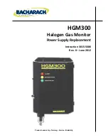
HGM300 Power Supply Replacement
P/N 3015-5686 Rev 0
7
Step
Description
5
Carefully remove the five (5) screws holding the Power Supply board to the back of the enclosure. Two
screws are located at the top of the board, two are at the bottom, and one is in the middle of the
board. Set these screws aside for later installation of the new board.
6
Carefully remove the old Power Supply Board. Dispose of it according to local laws and practices.
7
Carefully install the new Power Supply board by aligning the five holes on the board to the five stand-
offs on the back of the enclosure. Use the five screws you removed in the previous step to secure the
new board to the enclosure. Do not over-tighten the screws.
8
Replace all cables and connectors to their original locations. This includes the two input power
connectors, the power supply connector to the pump, and the two power supply connectors to the
main board. When installing these connectors, do not use excessive force as this could bend the
connector pins and/or damage the connectors.
9
Restore power to the HGM300.
10
Confirm normal operation to ensure that the power supply has been replaced correctly.
WARNING:
Drilling holes in the HGM300 enclosure will void the warranty. Please
use knockouts provided for electrical connections. Drilling into the box will void
the warranty.
WARNING:
Electrical installation should be performed by a certified electrician and
should comply with all applicable local, state, and federal electrical safety codes.
WARNING:
Under no circumstances should this instrument be operated without
connection to a protective ground. Doing so poses a potential shock hazard and is
also a violation of electrical safety standards applicable to this type of equipment.
∇
∇
∇


