background image

INSTALLATION INSTRUCTIONS

1

8

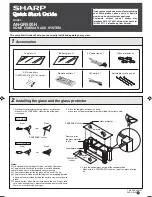
Attach Joining Plate to Column

i. Connect together four item C3 with item C2 onto each item C1 using item C4.
ii. Lay items B1 on the floor and slide two item C1 onto each item B1.

IMPORTANT:

Make sure the end with M8 threads 

are at the bottom of the columns. 

ii.

i.

C1

C2

C3

C4

C2

C1

C3

B1

C1

B1

C1

Содержание System X BT8375

Страница 1: ...ing patterns Tool less micro adjustments for seamless screen alignment Easy to use angle adjustment with a range up to 45º Universal screen position spacer to speed up the installation process Integrated cable management Safety screws help prevent unauthorised removal of screens FEATURES INSTALLATION TOOLS REQUIRED CONTENTS Installation Safety Notes 2 Parts List 4 Installation Instructions 8 Produ...

Страница 2: ......

Страница 3: ......

Страница 4: ... M8 SLIDING NUT M8 x 12mm SCREW 1 B1 4 2 2 B2 1 B4 VERTICAL COLUMN PLASTIC SLOT INSERT END CAP 4 B5 16 B6 B7 COLUMN JOINER GRUB SCREW B8 1 C1 8 C2 4 C3 JOINING PLATE M8 SLIDING NUT M8 x 12mm SCREW C4 1 5AF HEX KEY 1 D1 2 D2 MOUNTING RAIL END CAP PART NAME ITEM QTY PER PACK PART NAME ITEM QTY PER PACK PART NAME ITEM QTY PER PACK BT8390 300 Length 300cm Supplied with the BT8380 060 Supplied with the...

Страница 5: ...m SCREW M5 x 6mm SCREW G5 1 G6 1 G7 1 G8 4AF HEX KEY 3AF HEX KEY 5AF LONG HEX KEY Only supplied with the BT8390 VESA400MAP Please refer to individual parts list for more information QTY PER PACK Interface Arm Kit Screen Fixing Kit OPTIONAL INTERFACE ADAPTOR ARMS C B A D E F G H I J SPACER F BT8390 SP BT7564 BT7565 BT7566 F1 G1 G2 G1 G2 G6 G8 G7 G3 H 2 H1 4 H2 PART NAME ITEM ADAPTOR ARMS M8 x 12mm ...

Страница 6: ...AL ACCESSORIES AV Component Shelves Insert 2 x item B5 into item B1 front slots Mount a B Tech Shelf BT7032 BT7033 BT7863 by fastening item B6 to item B5 Use a BT8390 SA shelf adaptor to mount shelves directly under or over the horizontal mounting rails Attach the BT8390 CMC cable management clips directly to item D1 to orgainse screen cables for a neat and tidy installation BT8390 CMC Cable Manag...

Страница 7: ...the back IMPORTANT Joining bars should be inserted into the non threaded end of the 180cm column x THREADS THREADED B1 B7 OPTIONAL EXTENDING THE COLUMNS ii The two joining bars with grub screws in the front of the column The two joining bars with hex bolts in the rear of the column B1 B1 B7 Tighten hex bolts by hand Finish tightening using a 10mm spanner Back of Column Front of Column ...

Страница 8: ... i Connect together four item C3 with item C2 onto each item C1 using item C4 ii Lay items B1 on the floor and slide two item C1 onto each item B1 IMPORTANT Make sure the end with M8 threads are at the bottom of the columns ii i C1 C2 C3 C4 C2 C1 C3 B1 C1 B1 C1 ...

Страница 9: ...em F1 to set the distance between items C1 on item B1 according to the screen size Once set tighten item C3 with item C4 F1 F1 C1 C1 B1 C1 Leave at least a 5mm gap at top of column for item B2 ADJUSTMENT KNOB C4 C3 ...

Страница 10: ...tem C1 attachment insert 4 x item C2 into item D1 Two in the 2nd slot two in the bottom slot ii To attach item E1 to item D1 insert 4 x item E5 into the end of the rail Two in each centre slot 10 E5 C2 D1 C2 i Column Joining Plate Assembly ii Angle Adjustment Connector Assembly E5 ...

Страница 11: ... D1 D1 E1 E2 E3 E2 E3 i Assemble items E2 and E3 to item E1 Do not fully tighten the screws and washers i ii E6 E1 D1 D1 Note The rail fixing positions to use on part E1 are dependent on the size of screens being used For help with the rail fixing postion contact technical btechavmounts co uk Please state the screen size screen depth rail length and curve angle of the installation Fixing positions...

Страница 12: ...tem C1 fasten item C3 into the inserted items C2 attaching item B1 to item D1 To ensure straight assembly of item B1 make sure the distance of items C1 to the end of item D1 are set the same on each rail B1 D1 C3 C1 Assemble as shown C3 B1 C2 D1 C1 BACK C4 Equal distance to end of rail CORRECT WRONG D1 D1 x ...

Страница 13: ...5 Assemble Bases to Columns 13 Attach item A1 to item B1 using items A2 Once bases are fixed to columns return stand to upright position THREADED A1 A2 A3 B1 ...

Страница 14: ...14 E6 Set the angle required on item E1 and fully tighten all screws with item E6 E1 6 Fix Angle ...

Страница 15: ...Bolt stand to the floor 15 Pre drill holes in floor and using suitable ground anchor fixings not supplied fix stand to floor 7 CONCRETE FLOOR GROUND ANCHOR A1 ...

Страница 16: ...spacers for screens with recessed fixings SCREEN SCREEN SCREEN FIXING KIT Attach Interface Arms to Screen BT8390 VESA400MAF Arms NOTE Portrait mounting shown For landscape mounting attach adaptor arms horizontally Using Interface Adaptor Arms BOTTOM TOP SCREEN SCREEN FIXING KIT G1 G2 H1 H2 A F G2 G1 ...

Страница 17: ...ws The 3 notches show the position for interface fixings at 400mm 500mm and 600mm SCREWS G6 iii Fix item G3 inbetween items G1 G2 for easy lateral adjustment of the screen G3 G6 G4 G4 Distance between interface holes G3 G4 G2 G1 G2 G1 SCREEN FIXING KIT INTERFACE ARM RIGHT INTERFACE ARM LEFT i Attach the items G1 G2 to the back of the screen using the screen fixing items A F Ensure the arms are pos...

Страница 18: ...18 8 Hook Screen onto the Stand Hook the first screen centrally onto the bottom rail and align screen with the horizontal centre of the trolley stand D1 SCREEN G2 G1 SCREEN ...

Страница 19: ... screens and align screens accordingly Lateral Adjustment X axis i After mounting each screen use the micro adjustment knobs on the interface arms to level and align screen 9 Align screen HEIGHT ADJUSTMENT KNOB DEPTH ADJUSTMENT KNOBS ...

Страница 20: ...wn row by row Adjustment knobs are also compatible with 6mm allen key Adjustment lines to help with accurate Y axis screen alignment Total Y axis adjustment is 20mm Total Z axis adjustment is 20mm Total Y axis adjustment is 20mm Total Z axis adjustment is 25mm Note Light pressure in the desired direction of travel will assist in the adjustment of knobs when using heavier screens Use Height Adjustm...

Страница 21: ...ut To prevent interface arms from popping out fully insert and tighten item G5 at the padlock symbol at the bottom of iitems G1 G2 G5 Servicing Screens Pop Out Arms only Note Ensure pop out function is not disabled see below Push centrally at the left and right of the screen to pop out the mount The screen will rest in the open position for servicing Parts G1 G2 popped out G2 G1 G7 G5 Push Push IM...

Страница 22: ... if possible routed down the backs of item B1 partially clip on items B3 this allows easy removal if more cables need adding Once satisfied all cables are fitted clip items B3 on fully Fit items D2 to items D1 Fit items B2 to items B1 With a knife cut to length items B4 and slot into the front and sides of item B1 13 B4 B4 B1 D2 ...

Страница 23: ... 6mm 426mm 400mm 300mm 200mm 100mm 20mm 40 1mm 8 4mm 6 4mm 432 8mm 50mm 150mm 250mm 350mm 30mm 140mm 8mm 49 7mm Tolerance 1mm 193 6mm 30mm 237 2mm Tolerance 1mm 10mm Depth Adjustment 10mm Depth Adjustment 434 4mm 68 7mm Closed depth 100mm 200mm 300mm 400mm 426mm 6mm 146 8mm 280mm 65mm 18 8mm 50mm 150mm 250mm 350mm 451 6mm 110 9mm 100 7mm 6mm 240mm 8 4mm 50mm 105mm 10 5mm 25mm 50mm 165mm 174mm 86mm...

Страница 24: ...019 B Tech International Design and Manufacturing Limited All rights reserved B Tech AV Mounts is a division of B Tech International Design Manufacturing Ltd B Tech Better By Design System X are registered trademarks of B Tech International Design Manufacturing Ltd All other brands and product names are trademarks of their respective owners Photographs are for illustrative purposes only E OE ...

Отзывы: