40429 Brickyard Drive • Madera, CA 93636 • USA
559.438.5800 • FAX 559.438.5900
www.bklighting.com • [email protected]
B-K LIGHTING
RELEASED DATE
04/21/2021
REFERENCE NUMBER
INS-2845-00
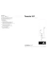
10"
(254mm)
"A/D" CAP
3" Dia.
(76mm)
2 11/16"
(68mm)
"B"/"E" CAP
(203mm)
8"
(76mm)
3" Dia.
2 11/16"
(68mm)
"C" CAP
(178mm)
7"
(76mm)
3" Dia.
Patented 360HD™
Mounting System
"B"/"E" CAP
3"
(76mm)
1"
(25mm)
"A"/"D" CAP
3"
(76mm)
5"
(127mm)
"C" CAP
2"
(51mm)
2 11/16"
(68mm)
1. Mount fixture onto suitable enclosure
according to designed lighting plan.
2. Secure ½” NPS stem to mounting option.
Secure with provided locknut if applicable.
3. Make watertight connections from remote
driver to fixture leads using waterproof wire
connectors (by others).
See wiring diagram.
Fixture Installation
YOSEMITE SERIES
Integral -LED
Standard Installation
4. Pull branch circuit wiring. Make watertight
connections from branch circuit wiring to
fixture leads using waterproof wire connectors
(by others) in splice location as per NEC.
UL Listed splice location required. Connect
incoming green ground wire to ground wire
from fixture.
See wiring diagram.
WIRING DIAGRAM
WIRING DIAGRAM (0-10)
All line voltage connections must be made
in compliance with the National Electrical
Code. Failure to do so will void warranty.
LINE
GROUND
GROUND
FIXTURE
COM
LINE
COM
FIXTURE
LINE
COM
GROUND
DIM +
DIM -
IMPORTANT SAFETY INFORMATION LISTED ON REVERSE
READ, FOLLOW, AND SAVE ALL SAFETY AND INSTALLATION
INSTRUCTIONS
1. Loosen three (3) captive #6-32 screws
securing cap/socket assembly with a 7/64”
allen wrench.
NOTE: Only one end cap (without ACV) is
removable.
2. Carefully pull out end cap assembly. LED is
still attached to leads.
Do not pull on connector or wiring. Handle
with care.
LED and Optic Replacement