manualshive.com logo in svg
background image

RELEASE DATE

12-19-16

REFERENCE


NUMBER

INS-2388-00

40429 Brickyard Drive • Madera, CA 93636 • USA

559.438.5800 • FAX 559.438.5900 

www.bklighting.com • [email protected]

B-K LIGHTING

IMPORTANT SAFETY INFORMATION LISTED ON REVERSE

READ, FOLLOW, AND SAVE ALL SAFETY AND INSTALLATION INSTRUCTIONS

HP

2

 SERIES™

12W-24W Integral Driver - Solid State LED

Installation Instructions

PROJECT:

TYPE:

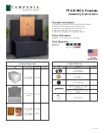
4.  Wipe inside of housing where HydroLock® plate 

will sit clean of debris before inserting patented 

HydroLock® plate on to junction box. Align 

HydroLock® plate with pins in housing and seat 

it firmly in place. 

Installation

6. Connect driver assembly to Patented 

HydroLock

®

 Barrier plate with quick disconnect.
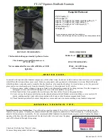
WIRING DIAGRAM

LINE

HYDRO-LOCK®

 PLATE

COM

GROUND

LINE

COM

GROUND

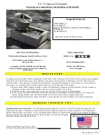
1.  Remove temporary cover.  

2.   Pull primary branch circuit wiring and dimmer 

wiring into junction box.  

3.   Make connections using silicone filled wire nuts 

(provided) to leads on the bottom of Patented 

HydroLock® Barrier Plate Assembly.  

See wiring 

diagram.

5.  Turn HydroLock®


Barrier Plate clockwise ¼” to 

lock.


Patented


HydroLock® Barrier Plate must be 

completely seated to ensure proper seal or 

water may intrude. This step must be done 

as stated or you will void your warranty.

7.  Lower driver assembly into HP2 housing.

8.  Attach driver assembly to housing by aligning 

keyhole notch under one (1) of three (3) #8 

screw heads.

9.  Tighten the Phillips screws to secure driver 

plate to housing.


For use with 12-24 watt dimming driver.

Содержание HP2 SERIES

Страница 1: ...d during servicing or relamping turn off power at fuse or circuit breaker before service The use of accessory equipment not recommended by the manufacturer or installed contrary to instructions may cause an unsafe condition The use of damaged components may cause an unsafe condition and void product warranty IMPORTANT SAFETY INFORMATION READ FOLLOW AND SAVE ALL SAFETY AND INSTALLATION INSTRUCTIONS...

Страница 2: ...ousing is level tighten screws on Stability Flange to secure housing to EMT Remove excess EMT as needed 7 Per DIG IT Guide backfill the gap between the bottom of housing and bottom of hole with sand for drainage Housing Installation Threaded Entry Side Flats 1 Connect branch conduit connectors By Others to the junction box using either the threaded conduit entries on the bottom of the junction box...

Страница 3: ...Patented HydroLock Barrier plate with quick disconnect WIRING DIAGRAM LINE HYDRO LOCK PLATE COM GROUND LINE COM GROUND 1 Remove temporary cover 2 Pull primary branch circuit wiring and dimmer wiring into junction box 3 Make connections using silicone filled wire nuts provided to leads on the bottom of Patented HydroLock Barrier Plate Assembly See wiring diagram 5 Turn HydroLock Barrier Plate clock...

Страница 4: ... REVERSE READ FOLLOW AND SAVE ALL SAFETY AND INSTALLATION INSTRUCTIONS 10 Remove any dirt or debris in O ring groove near top of housing Place O Ring inside of groove Failure to clean groove of debris will cause fixture to fail and void product warranty 12 Install faceplate using 1 8 Allen wrench and hand tighten the faceplate screws in a star pattern to 30 in lbs min Do not use a power tool to in...

Страница 5: ...come extremely hot Do not touch hot lens or fixture body Do not touch the lamp at any time Use a clean dry soft cloth to handle the lamp Oil from skin may damage the lamp and cause it to rupture Replace lamp only with correct wattage and type of lamp marked on fixture label All gaskets O rings and sealing surfaces must be kept clean during installation and service failure to do this may cause an u...

Страница 6: ...person in a manner consistent with its intended use and in compliance with the National Electrical Code Canadian Electrical Code and all Local and Provincial Codes Follow product label information and instructions Qualified Personnel with appropriate personal protective equipment must perform all servicing of this product Before wiring to power supply and during servicing turn off and lock out pow...

Страница 7: ...ner consistent with its intended use and in compliance with the National Electrical Code Canadian Electrical Code and all Local and Provincial Codes Follow product label information and instructions Qualified Personnel with appropriate personal protective equipment must perform all servicing of this product Before wiring to power supply and during servicing turn off and lock out power at fuse or c...

Отзывы: