background image


บริษัท เอดีดี เฟอร์เนส จ ำกัด


                                                  ADD FURNACE CO.,LTD.


                                                    44 ซอยบรมราชชนนี


  70 ถนนบรมรำชชนนี แขวงศำลำธรรมสพน์ เขตทวีวัฒนำ กรุงเทพฯ 10170


โทร

: 02-888-3472  

โทร

:


ออกแบ

:

08-08-170-170 


แฟกซ์

: 02-888-3258 

                                                                 https://www.add-furnace.com   E-mail: 

sales@add-furnace.com


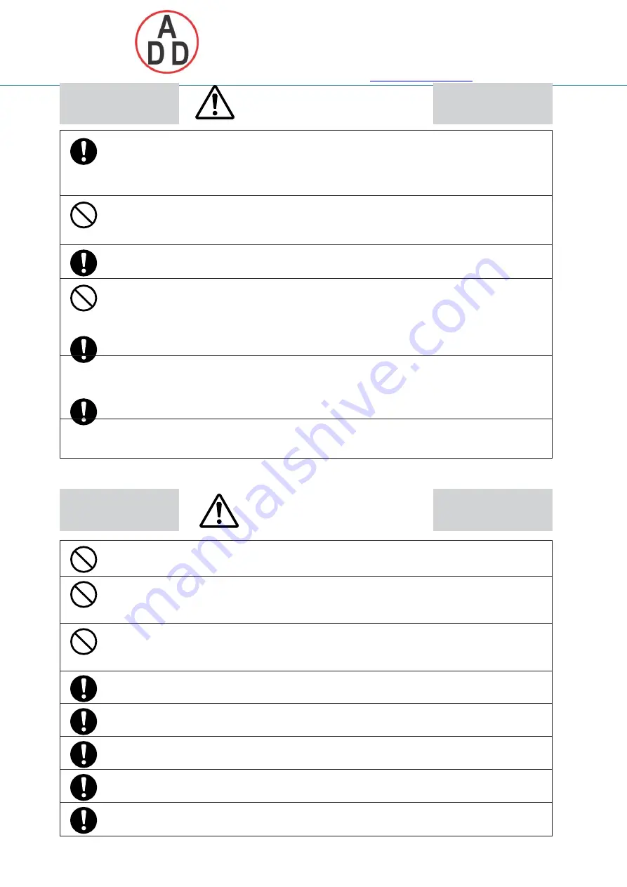
WARNING


When using combustible gas, install the device upstream of the safety


shut off valve. If air somehow enters the piping, and the sensor makes a spark 
due to some cause like a lightning strike when an explosive mixture is 
present, an explosion could occur inside the pipe.


On flanged models, do not use the device or installed pipes as a footrest. 
Doing so might damage the device or piping, or cause a slip which might 
result in injury.


Flanged models are heavy. Dropping them on your feet may cause injury.


The device is intended for use with natural gas and air.


Do not use the device for other types of gases. Use of the gases having an 
ignition temperature lower than 365°C may cause an internal pipe explosion. 
A heater incorporated in a sensor could act as an ignition source if air has 
entered the piping and explosive mixed gas is produced.


Use the analog outputs and alarm contact outputs on the device for 
monitoring the gas flow rate of a burner or other equipment. Do not use these 
outputs in applications where safety will be impaired when an analog output 
abnormality or alarm contact output malfunction occurs.


Before wiring the device, be sure to turn the power OFF. Failure to do so might 
cause electric shock.


CAUTION


This device is a precision instrument. Do not drop it nor subject it to shock. 
Doing so might damage the device.


Do not peel off the pipe connection port seals until immediately before you 
connect the piping. Doing so might allow foreign objects to enter the 
connector port and cause defective operation.


On rusty, welding fumes, slag, water droplet, oil mist or dusty piping, install a 
filter upstream to prevent foreign matter from entering the device. Foreign 
matter may cause faulty operation.


When wiring, take care not to tug on the display. The components inside 
might become damaged.


Be sure to use only rated fuses for replacement. Use of a non-rated fuse 
prevents the safety circuit from functioning properly.


Be sure to check that the wiring is correct before you turn the power ON. 
Incorrect wiring may cause damage or malfunction.


Connect the power supply last. Otherwise touching terminals by mistake may 
cause electric shock or damage the device.


Make sure that the load to be connected to terminals does not exceed the 
rating indicated in the specifications.


ii


Содержание CMG Series

Страница 1: ...CP UM 5477E TM CMG Series Gas Flow Monitor USA Model User s Manual Thank you for purchasing the CMG Series Gas Flow Monitor This manual contains information for ensuring the correct use of the CMG Series It also provides necessary infor mation for installation maintenance and troubleshooting This manual should be read by those who design and maintain equipment that uses the CMG Series Be sure to k...

Страница 2: ...lingmachines Aeronautical aerospace machines Control devices for nuclear reactors Never use this product in applications where human safety may be put at risk RESTRICTIONS ON USE NOTICE Be sure that the user receives this manual before the product is used Copying or duplicating this user s manual in part or in whole is forbid den The information and specifications in this manual are subject to cha...

Страница 3: ...ntended to ensure the safe and correct use of this prod uct to prevent injury to the operator and others and to prevent damage to proper ty Be sure to observe these safety precautions Examples Triangles warn the user of a possible danger that may be caused by wrongful operation or misuse of this product These icons graphically represent the actual danger The example on the left warns the user of t...

Страница 4: ...the gas flow rate of a burner or other equipment Do not use these outputs in applications where safety will be impaired when an analog output abnormality or alarm contact output malfunction occurs Before wiring the device be sure to turn the power OFF Failure to do so might cause electric shock CAUTION This device is a precision instrument Do not drop it nor subject it to shock Doing so might dama...

Страница 5: ...1 Check the model number to make sure you received the correct product 2 Check for any obvious damage 3 Check the contents of the package against the packing list to make sure that all items are included Handle the CMG series and its accessories with care to prevent damage or loss ofparts If there is some problem with your order please contact your dealer immediately Name Model No Q ty Remarks Bod...

Страница 6: ...CTIONS OF PARTS Chapter 3 MOUNTING AND WIRING Mounting 5 Pipes 6 Wiring 9 Chapter 4 OPERATION Displaying the flow rate 12 Resetting alarms 13 Resetting the integrated flow rate 13 Displaying the total flow rate 14 Chapter 5 ADVANCED OPERATION 5 1 Function Setup 15 Setting operation 15 Function setup item list 16 5 2 Parameter Setup 17 Setting operation 17 Parameter setup item list 18 Chapter 6 MAI...

Страница 7: ...flow rate management of units Factory setting is 32 F 1 atmosphere The reference temperature can be selected from 41 F 50 F 59 F 68 F and 77 F according to the function settings Installation of the compact and high precision CMG is simple It can be mounted in any direction as the direction of the display can be changed Gas flow rate can be measured and managed easily on the digital flow rate displ...

Страница 8: ...0 O 5 000 CFH normal 1 V Output 1 O O O O 4 to 20mA Event VI Operating pressure 0 O O O O 0 to 14 5psi 100kPa VII Option 1 0 O O O O None VIII Power supply 0 O O O O 24 Vdc IX Option 2 0A O O O O Fixed Air model Talble Selection Description Model Number CMG Gas Flow Monitor I Piping size 15 O 1 2 inch 25 O 1 inch 40 O 1 1 2 inch 50 O 1 2 inch II Connection method 2 O O O O NPT thread III Gas type ...

Страница 9: ...tegrated flow rate ALARM RESET ENT display DISP key Use this key to switch between instantaneous flow rate display and integrated flow rate display and from setup mode to instantaneous flow rate display key Use this key to increment a value key Use this key to decrement a value Also use it to switch to the function setup mode key Use this key to feed digits when changing setting values Also use it...

Страница 10: ...ipe side to connect the piping When connecting a flanged device first check that the piping is not tilted or off center before installing Failure to do so might causeleakage To prevent vibration of the device attach the pipe securely Do not peel the protective seals from the display before use When performing work on the device tools may accidentally bump against the display and scratch it When us...

Страница 11: ...olvents 6 Vibration or shock 7 Direct sunlight 8 Direct splashing by rain or water 9 Splashing by fluids e g oil chemicals 10 Strong magnetic or electrical fields 11 Where there is a pulsating flow 1 One cause is flexible piping regardless of the material with an accordion shape inner surface and a length of 500mm or more Flexible piping such as a rubber hose with a flat inner surface does not cau...

Страница 12: ...lingthedevice be suretoflushtheupstreamand downstreampipingthoroughly to removeweldingfume particulate anddust CMG 2 Be sure to wipe the inside Upstream side of piping Downstream side of 2 piping of the pipe to be directly connected to this device 3 After the above two operations are complete check to be sure that there is no welding fume particulate or dust and then install the device Handling Pr...

Страница 13: ... be used with the display facing up 90 Right Right Right Wrong Handling Precautions The length of the required straight pipe connection varies according to the model number For details see Individual specifications page 23 Screw connection Coating sealant Coat with an appropriate amount of sealant Do not coat the top two threads of the screw Remove any dirt burrs or piping cutting oil from inside ...

Страница 14: ...OUNTING AND WIRING Connecting pipes Connect pipes while gripping the hexagonal section of the pipe connection port on the body with a wrench Pipe Handling Precautions Do not grip the display or sensor terminal section Doing so might damage the body or cause leakage Do not tighten the pipe at a torque that exceeds themaximum tightening torque Model No Max Tightening Torque CMG152 50N m CMG252 125N ...

Страница 15: ...label on the CMG Symbol Meaning Direct current Removing the operation panel display Required tool Phillips screwdriver 1 Loosen the four screws on the operation panel display using the Phillips screwdriver 2 Gently lift up the operation panel display and disconnect its power lead connectors Wiring Internal circuit CN1 Terminal 1 Terminal 2 24Vdc COM Terminal 3 OUTPUT 4 to 20mAdc output Terminal 4 ...

Страница 16: ...l connector Yamatake model PA4 N2 PA4 N4 or equivalent product for reliable sealing When wiring to terminal 2 COM wire the analog output lead separately from the power lead Otherwise a voltage drop caused by the power current may influence the accuracy of the analog output Take care that event output 2 the open collector output does not exceed the output rating of this device When driving a relay ...

Страница 17: ...necessarily twisted or pinched when fitting the sections together Prevent the leads connecting the sensor terminal section and the operation panel display from being damaged Do not rotate the operation panel display beyond 180 to the left or right This section may be rotated to the left or right if it is mounted upside down Use an operation panel display and a sensor terminal section with the same...

Страница 18: ...rate When the power is turned ON the CFH indicator lights to indicate the instantaneous flow rate To display the integrated flow rate press the DISP key The CF indicator lights to indicate the integrated flow rate The display is a 4 digit display However the integrated flow rate is displayed as eight digits divided into the first four digits and the last four digits In all an integrated flow rateu...

Страница 19: ... Resetting alarms When a flow rate alarm detection condition is selected an item from 1 to 5 in function setup item C see page 19 an alarm is set To reset the alarm press the RESET key The alarm indicator goes out and the alarm output relay turns OFF Handling Precautions Alarms are also reset by turning the power OFF The alarm recurs after the alarm occurrence wait time when the flow rate exceeds ...

Страница 20: ...ey again within five seconds while it is displayed The first four digit display You can also alternately display the first four digits and the last four digits by using the key repeatedly Handling Precautions The total flow rate indication returns to after is exceeded Integrated flow rate and total flow rate values are held in memory even if the power is turned OFF On models that display values do...

Страница 21: ...desired setup item and press the key The current setting blinks on the 7 segment display 4 Press the or key to select the desired setting 5 When the desired setting has been selected press the key to finalize the setting After approx one second the item number is redisplayed and the setting is updated 6 If there are other required setup items return to step 3 above to repeat the procedure If there...

Страница 22: ...curs 3 ON when upper limit alarm or lower limit alarm occurs 4 ON when integration event occurs 3 C Event output 2 open collector function assignment 0 Not used OFF at all times 1 ON when upper limit alarm occurs 2 ON when lower limit alarm occurs 3 ON when upper limit alarm or lower limit alarm occurs 4 ON when integration event occurs 5 Integrated pulse output 5 C Flow rate alarm reset method se...

Страница 23: ...em and press the key The current setting blinks on the segment display 4 Press the or key to change to the desired value The digit to be changed can be moved by using the key 5 When the desired setting has been selected press the key to finalize the setting After approx one second the item number is redisplayed and the setting is updated 6 If there are other required setup items return to step 3 a...

Страница 24: ...s 0 0 to 999 9s 6 P L Integration event setup lower four digits 0 CF 0 to 99 999 999 CF Value set is valid only when selecting integration event output in either C or C of function setup 7 P H Integration event setup upper four digits 8 C L Integration reset delay time 10 0s 0 0 to 999 9s Value set is valid only when selecting automatic reset by integration reset delay in C of function setup 9 Ins...

Страница 25: ... 3258 https www add furnace com E mail sales add furnace com OFF Hysteresis OFF Hysteresis Chapter 5 APPLICATION OPERATION Instantaneous flow rate upper limit alarm operation ON Instantaneous flow rate upper limit alarm value Instantaneous flow rate Instantaneous flow rate lower limit alarm operation ON Instantaneous flow rate lower limit alarm value Instantaneous flow rate 19 ...

Страница 26: ... alternately with the flow rate value The probable cause is an error in the memory which is individually adjusted for each sensor is displayed but the operation continues with provisional data in spite of the error Readjustment by Yamatake is necessary The display is other than including a minus display even though the instantaneous flow rate should be zero Check the shut off valve and piping for ...

Страница 27: ...se prevents the safety circuit from functioning properly Needed items Phillips screwdriver Fuse Made by Cooper Bussmann U K Ltd Model No S504 500mA 250V 0 5A Made by Littelfuse Model No 218 500 250V 0 5A Standard IEC127 Fuse blowout speed Time lag Rated voltage 250V Rated current 0 5A Replacement procedure 1 Loosen the four screws on the operation panel display 2 Gently lift up the operation panel...

Страница 28: ...ut 4 to 20mAdc Output range 0 to 400 of measurement range upper limit scalable Accuracy 0 5 FS Load resistance 300 max Event output 1 1a contact closes at event generation Contact rating 250Vac 30Vdc 5A resistance load Mechanical life 20 million cycles Electrical life 70 000 cycles Event output 2 Output configuration NPN open collector output Output rated 30V 50mA max When integrated pulse output ...

Страница 29: ...ter the decimal point for CFH is the same as that shown in the table 2 Normal refers to the volumetric flow rate CFH after converting to 32 F 1 atmosphere 3 The measurement range is the flow rate range in which instantaneous flow rate display accuracy is stipulated 4 Straight pipe longer than the length specified above may be required depending on the pipe shape or other devices mounted on the pip...

Страница 30: ...nlarging pipe is used Downstream side reduced Reducing pipe is used Upstream side reduced Reducing pipe is used Downstream side enlarged Enlarging pipe is used Valves fully open D inner dia of connecting pipe Upstream Downstream Handling Precautions In case of globe butterfly or needle valves which cause disturbance or fluctuations to the flow a straight pipe length of more than 30D is required In...

Страница 31: ...si 1 atmosphere 35 25 15 psi 15 50 psi 75 psi 100 psi 0 0 400 800 1200 Flow rate CFH normal CMG402 Supplied pressure 120 0 psi 1 atmosphere 80 15 psi 40 50 psi 75 psi 0 0 500 1500 2500 Flow rate CFH normal 100 psi 3500 120 CMG502 Supplied pressure 0 psi 1 atmosphere 80 40 0 0 2000 4000 Flow rate CFH normal 15 psi 50 psi 75 psi 100 psi 6000 Note The pressure loss varies with the supplied pressure D...

Страница 32: ...0 แฟกซ 02 888 3258 https www add furnace com E mail sales add furnace com CMG252 1NPT CMG152 1 2NPT 2 HEX1 81 0 0 06 Chapter 7 SPECIFICATIONS External dimensions CMG152 252 Unit inch G 1 2 thread with min depth 0 4 CMG402 502 G 1 2 thread with min depth 0 4 26 0 98 0 98 3 94 CMG502 2NPT CMG402 1 2NPT 0 98 0 98 6 69 4 41 2 38 3 30 2 38 3 70 5 18 4 61 6 81 1 06 1 06 ...

Страница 33: ...มรำชชนนี แขวงศำลำธรรมสพน เขตทวีวัฒนำ กรุงเทพฯ 10170 โทร 02 888 3472 โทร ออกแบบ 08 08 170 170 แฟกซ 02 888 3258 https www add furnace com E mail sales add furnace com Revision History Printed Date Manual Number Edition Revised pages Description Apr 2007 CP UM 5477E 1st Edition ...

Страница 34: ... 888 3472 โทร ออกแบบ 08 08 170 170 แฟกซ 02 888 3258 https www add furnace com E mail sales add furnace com Advanced Automation Company 1 12 2 Kawana Fujisawa Kanagawa 251 8522 Japan URL http www azbil com Printed on recycled paper 07 Printed in Japan 1st Edition Issued in Apr 2007 Specifications are subject to change without notice ...

Отзывы: