


1
บริษัท เอดีดี เฟอร์เนส จ ำกัด
ADD FURNACE CO.,LTD.
44 ซอยบรมราชชนนี
70 ถนนบรมรำชชนนี แขวงศำลำธรรมสพน์ เขตทวีวัฒนำ กรุงเทพฯ 10170
โทร
: 02-888-3472
โทร
:
ออกแบ
บ
:
08-08-170-170
แฟกซ์
: 02-888-3258
https://www.add-furnace.com E-mail:
No. CP-SS-1896E
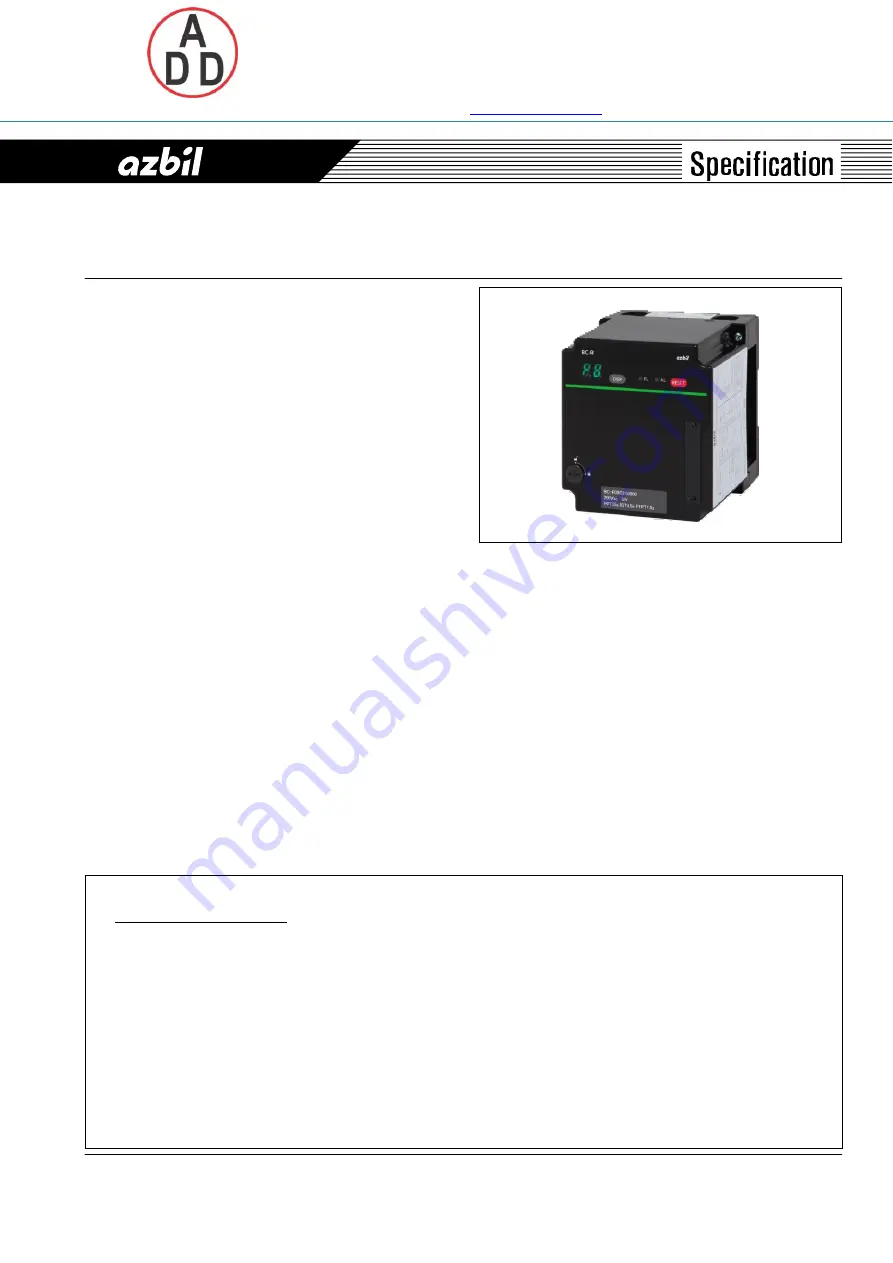
BC-R35 Series
Burner Controllers
Summary
BC-R35 Series burner controllers are combustion safety
controllers specifically designed for batch operation
(systems which start and stop at least once within 24 hours). They
ensure safety by automatically controlling the ignition,
combustion monitoring, and fuel shutoff of oil and gas
burners with proportional control. They are also equipped with
a 7-segment display that can be used in maintenance, a trial
operation mode that is convenient for trial-run operation
and adjustment, and other features.
Add i t iona l l y, t he BC - R35 i s equ ipped w i t h host
communications (RS-485) and Smart Loader Package
functions, allowing troubleshooting and more detailed
observation of status.
Features
Compliant with JIS standards
•
Safe construction of combustion systems and equipment
-
Pre-purge and ignition timing in compliance with JIS B
8407:2012 (forced-air burners) and JIS B 8415:2008
(combustion equipment in compliance with the safety
principles for industrial incinerators).
-
POC (proof of closure), based on shutoff valve closure
confirmation switch input
•
JIS-compliant burner controller safety design
-
Safety design in compliance with JIS C 9730 (automatic
electrical controls for household and similar use)
-
EN 298 compliance (certification pending)
Easy mounting and replacement
•
DIN rail mounting
-
Easily mountable in the same way as other control
devices and control relays
•
Uses sub-base structure
-
Structure separates the sub-base from the main unit It is
possible to change only the main unit, leaving the wired-in
sub-base in place
Precautions on equipment instrumentation
Extensive communications with external devices
•
Equipped with a 7-segment display
-
7-segment display for sequence codes and warning
codes
-
Press the DISP switch to display the flame voltage.
•
External status output
-
States such as ignition failure, flame failure, and
combustion detected are output digitally (and used as
panel displays)
•
Warning reset by contact input
•
Equipped with a trial-run operation mode
-
The control motor can be forced to full open and full closed
outputs to adjust the high and low fire positions and check
the airflow volume
•
Equipped with host communications (RS-485), allowing
remote observation of status
•
Status checking by the Smart Loader Package
(1)
The equipment used in the combustion safety system was designed with careful consideration of laws, standards, safety guidelines, and
the like. If the system is designed to a foreign specification, refer to laws and standards in the relevant country.
Main Safety Policies in Japan
-
Technical policy on Safety Standards for Combustion Equipment in Industrial Furnaces: Ministry of Health, Labour and Welfare
-
Combustion equipment in compliance with the safety principles for industrial incinerators - JIS B 8415
-
Forced Draught Burners - Part 1: Gas Burners - JIS B 8407-1
-
Forced Draught Burners - Part 2: Oil Burners - JIS B 8407-2
-
The index of safety technology of industrial gas combustion equipment: Japan Gas Association
-
Index of safety technology of gas boiler combustion facilities: Japan Gas Association
(2)
This device monitors for failures in the relay contacts used for combustion load (IG, PV, MV) output. An E09 error is output if a voltage
occurs at a load terminal, due to a ground fault or wiring error, when this device is not outputting a load. If an E09 error occurs when this
device is installed, recheck the wiring and eliminate the factors causing the error.
(3)
If the wiring from this device exceeds the recommended length, prevent malfunction due to the effects of external noise by running wires
from the control panel to the casing through a conduit, keeping a distance between power lines and input lines, and other measures.
Check the operation of the system on installation.
(4)
A reset signal must always be input near the equipment (burner, etc.), not remotely.
If a reset is input while it is not possible to confirm safety, there is the risk of explosion.


