27
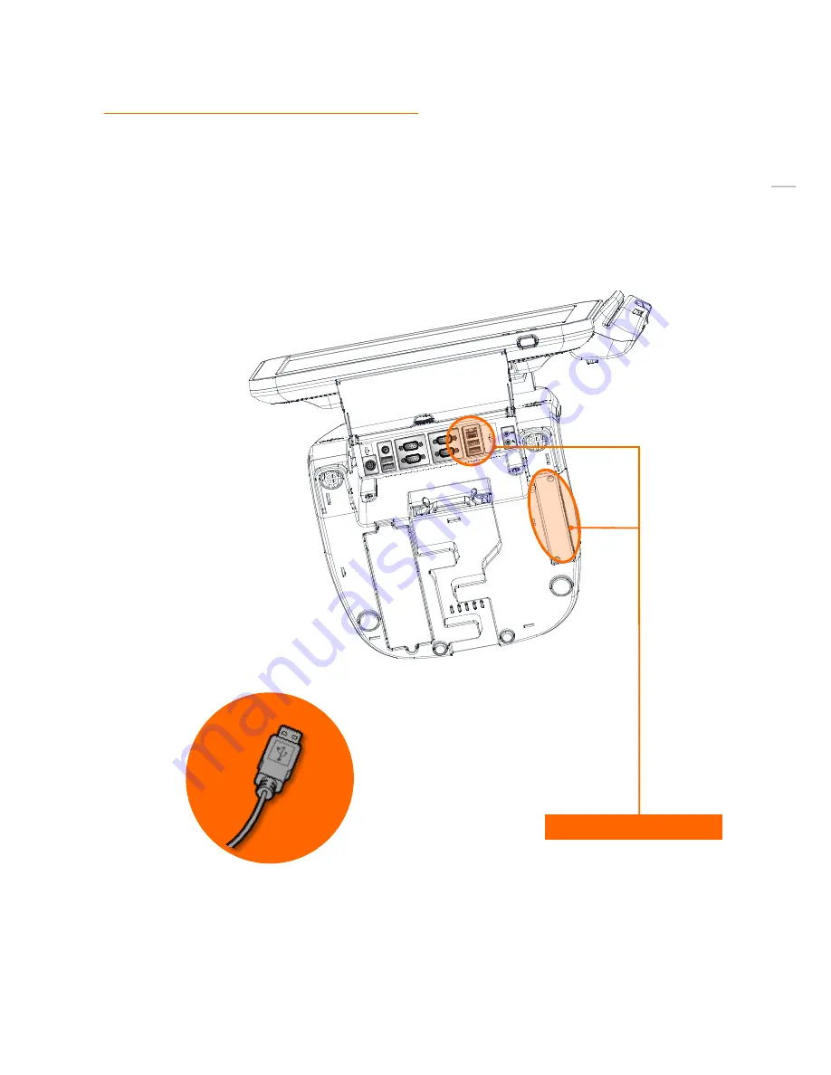
(8) Setting up: Connection USB Port
USB ports are provided in the POS unit, two at the rear I/O and four at the side, all of which support the standard USB
2.0.
Some USB devices (optional devices) are only functional with specific driver software installed.
If multiple USB devices are used together, this may result in abnormal functionality.
Using a USB hub with external adapter for supplying power is recommended.
Dependent on the type of device, it is possible for the USB device to be recognized later than normal.
USB port (6port support)
Содержание POS2400
Страница 1: ...Point of sale system POS2400 User s manual PBUM 026E Rev001 131213 ...
Страница 17: ...17 Side view 1 I O port cover 2 USB port 3 Customer display Option 4 Storage Default SSD 2 1 4 2 3 ...
Страница 19: ...19 Standard I O port 1 2 ...
Страница 30: ...30 11 Setting up Printer Connection Connect printer cable to either Serial USB port as required ...
Страница 38: ...38 3 Side USB Board Side USB Board Connector Description A To Motherboard USB A ...
Страница 39: ...39 4 Power Switch Board Power Switch Board Connector Description A Power switch A ...
Страница 41: ...41 6 Drawer Port Board Drawer Port Board Connector Description A From Drawer Kicker B Cash Drawer port A B ...
Страница 45: ...45 6 OnboardTouch function Enable Disable selection USB_SEL 1 Disable Enable Default 1 ...
Страница 52: ...52 2 4 Launch PXE 0Prom Disable Configuration options Disabled Enabled ...
Страница 59: ...59 2 10 Hardware Monitor Smart Fan Mode configuration Smart Fan Mode select ...
Страница 61: ...61 2 11 Chipset ...
Страница 63: ...63 2 13 Boot Display Configuration ...
Страница 65: ...65 Color depth 24Bits Select color Depth for LVDS ...
Страница 66: ...66 2 15 South Bridge parameters Into South Bridge Subdiredtory ...
Страница 68: ...68 2 16 Boot ...
Страница 69: ...69 2 17 Security Administrator password Set administrator password User password Set User password ...
Страница 75: ...75 POS 2400ModulePOSSystemReplacement 1 Separating LCD module LCD module Step 1 Lift up the LCD display ...
Страница 77: ...77 Separating LCD module Step 5 Separate LCD monitor module LCD monitor module is now removed ...
Страница 83: ...83 Separating motherboard Step 4 Remove the 4 screws Step 5 Replace the motherboard ...


