Assembly
9
PLEASE DISPOSE OF THE PACKAGING RESPONSIBLY;
MUCH OF THE MATERIAL IS RECYCLABLE
The machine and its accessories will arrive coated with heavy
corrosion preventative grease and greased wax paper or plastic
wrapping. These will need to be cleaned from the machine, its
components and accessories prior to it being set up and
commissioned. Use water soluble de greaser to remove the
barrier grease. Be warned, it will stain if you splash it on
clothing etc. After cleaning, lightly coat the exposed metal
WARNING! WEAR OVERALLS, RUBBER GLOVES
AND EYE PROTECTION!
surfaces of the machine with a thin layer of light machine oil.
N.B If you used water soluble de greaser make sure you apply
this thin film sooner rather than later.
Please read the Instruction Manual prior to using your new
machine; as well as the installation procedure, there are
daily and periodic maintenance recommendations to help
you keep your machine on top line and prolong its life.
Keep this instruction manual readily accessible for any
others who may also be required to use the machine.
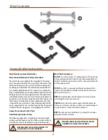
Having unpacked your machine and its accessories, please
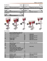
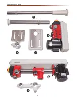
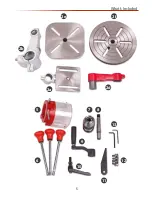
check the contents against the equipment list ”What’s Included”,
if there are any discrepancies, please contact Axminster Tool
Centre using the procedures laid down on our website.
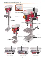
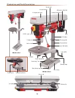
Please read through the section entitled illustration and
parts description, to identify the parts quickly and easily.
WARNING! THE DRILL HEAD IS A HEAVY AND
SUBSTANTIAL PIECE OF MACHINERY, YOU ARE
ADVISED TO HAVE HELP TO LIFT IT CLEAR OF THE
BOX AND FIT IT TO THE COLUMN.
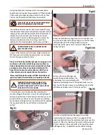
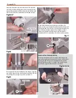
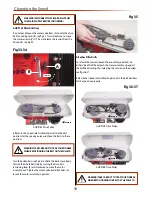
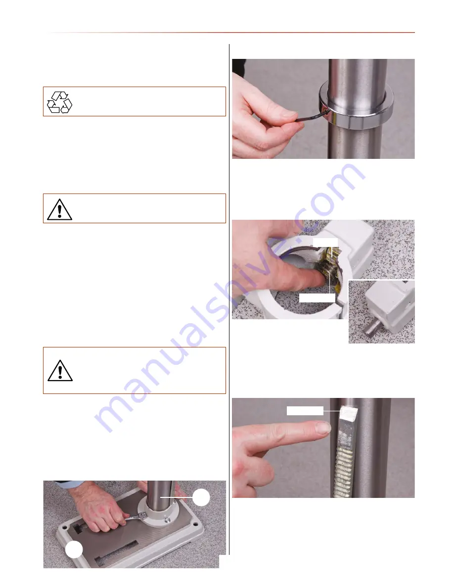
1. Place the base (3) on the bench or floor and place the
mounting flange of the column (1) onto the seating flange of
the base, align the holes. Use the four Hex bolts and secure the
column to the base, see fig 1. Loosen the grub screw holding
the chamfered retaining collar on the column with the supplied
Hex key, place it and the rise and fall rack assembly aside,
see fig 2.
Fig 01
Fig 02
2. Take the drill table mounting bracket arm (2,2a,2b,2c) and
twist the worm drive shaft with your fingers so that the whole
shaft protrudes from the casting and the worm gear
itself is clear of the square recess in the main body of the
casting (see fig 3).
Fig 03-04
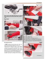
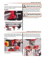
3. Pick up the rise and fall gear rack,
identify the top and the bottom, (the
rack gearing is cut asymmetrically, with
the gear cut extending closer to the bottom), make sure you
have the rack the right way up, as it will allow you to drive the
drill table up and down over its full range, see fig 5.
Fig 05
4. Fit the rise and fall rack into the square recess in the
mounting body casting, ensure that it is engaged with the
pinion, see figs 6 and lower the combined mechanism over the
column (1). Allow it to slide down the column until the rise and
fall rack is located in the cup chamfer in the top of the mount-
ing flange, see figs 7. Replace the cup chamfered retaining
3
1
Worm gear
Pinion
Top of rack
Worm gear shaft
Continues Over....
Содержание AHDP13B
Страница 4: ...What s Included 4 1 2 3 4a 2c 4 ...
Страница 5: ...What s Included 5 2b 2e 2d 2a 5 6 10 9 7 8 13 11 12 2f ...
Страница 24: ...Exploded Diagram Parts List 24 AHDP13B Bench Pillar Drill ZQJ4113A ...
Страница 26: ...Exploded Diagram Parts List 26 AHDP16B Bench Pillar Drill ZQJ4116Q ...
Страница 28: ...Exploded Diagram Parts List 28 AHDP16F Floor Pillar Drill ZQJ4116A ...
Страница 30: ...Exploded Diagram Parts List 30 AHRD16B Bench Radial Drill ZQJ3116 AHRD16F Floor Radial Drill ZQJ3116A ...
Страница 34: ...Wiring Diagram 34 ...
Страница 35: ...CE Certificate 35 AHDP13B Bench Pillar Drill ZQJ4113A AHDP16F Floor Pillar Drill ZQJ4116A ...
Страница 36: ...CE Certificate 36 AHDP16B Pillar Drill ZQJ4116Q ...
Страница 37: ...CE Certificate 37 AHRD16B Bench Radial Drill ZQJ3116 AHRD16F Floor Radial Drill ZQJ3116A ...
Страница 38: ...Notes 38 ...
Страница 39: ...Notes 39 ...


