background image

Assembly

6

Locate the bed extension (J) and the two Hex screws 
and spring/washers, (see fig 7) position the bed 
extension against the end of the lathe and line up 
the pre-drilled holes, (see figs 8-9). Place a washer and 
spring washer over the Hex screws and lightly screw 
them into the threaded holes, (see fig 10).

Optional Bed Extension

Release the tailstock clamping lever and position the 
tailstock across the join to align both beds, re clamp 
the tailstock in position and tighten both Hex screws. 
(see figs 11-12).  Both beds are now aligned.

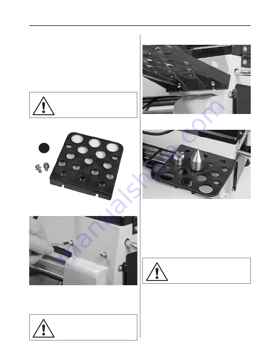
Fig 03

Fig 05

Fig 04

Fig 06

Locate the tool holder (I) the two Phillips screws and 
washers. (see fig 3) Place a washer over the screws 
and screw them into the two pre-drilled holes below 
the headstock, (see fig 4).

NOTE GIVE ADEQUATE GAP 
BETWEEN THE SCREW HEAD 
AND LATHE CASTING!

I

Line up the machined slots in the tool holder (I) 
and slide the holder down over Phillips screws then 
lightly tighten the screws to clamp the holder in 
place, (see figs 5-6).

Tool Holder

DON’T OVERTIGHTEN THE
PHILLIPS SCREWS AS THE 
HOLDER IS ONLY PLASTIC!

NOTE: DON’T TIGHTEN THE 
SCREWS AT THIS POINT!

NOTE: There are also two pre-drilled holes under 
the tailstock if you wish to mount the tool holder 
there.

Содержание AH-1218

Страница 1: ...Code 505021 Axminster Tool Centre Unit 10 Weycroft Avenue Axminster Devon EX13 5PH axminster co uk AH 1218 AH 1218VS Woodturning Lathes Code 505020...

Страница 2: ...n using this machine Fully read manual and safety instructions before use Eye protection should be worn Ear protection should be worn HAZARD Motor gets hot Dust mask should be worn Please read the Ins...

Страница 3: ...Prong Drive Centre 25mm F code 340106 1 No Axminster Standard 60 Live Centre G code 340203 1 No Push Rod H 1 No Tool Holder and two Phillips screws washers I 1 No User Manual Quantity Item Part 1 No B...

Страница 4: ...r hair in a long style wearing a cap safety helmet hairnet even a sweatband will minimise the possibility of your hair being caught up in the rotating parts of the tool likewise consideration should b...

Страница 5: ...ive coated with corrosion preventative grease This will need to be cleaned from the machine its components and accessories prior to it being set up Use coal oil paraffin or a proprietary de greaser to...

Страница 6: ...12 Both beds are now aligned Fig 03 Fig 05 Fig 04 Fig 06 Locate the tool holder I the two Phillips screws and washers see fig 3 Place a washer over the screws and screw them into the two pre drilled...

Страница 7: ...7 Assembly 7 Fig 07 Fig 08 Fig 10 Fig 09 Fig 11 Fig 12 J J Hex screw...

Страница 8: ...bed Tailstock Banjo arm NVR switch assembly Motor handle Push rod tool holder Motor handle lock Rubber foot 60 Live centre Index lock pin Index ring 4 Prong drive centre Tool rest lock Tailstock hand...

Страница 9: ...d slap the shroud down to stop the lathe in an emergency ON I and OFF O buttons Fig 15 Fig 16 Tailstock lock Tool holder Power cable hooks Tailstock barrel lock Speed control dial AH 1218VS Control bo...

Страница 10: ...giving a maximum of 965mm between centres Fig 17 Indexing assembly facility Fig 19 Motor pulley access door Index ring Index pointer Index locking pin Door knob spring lock Fig 18 Tailstock barrel wi...

Страница 11: ...ring set to position 24 The indexing facility is useful for fluted columns clock faces and accurate hole positioning The indexing ring has 24 positions 15 indexing using the index pin knob on top of t...

Страница 12: ...ing the Lathe Speed DISCONNECT THE LATHE FROM THE MAINS SUPPLY BEFORE CONTINUING 1 Open the motor pulley access door by pulling the door knob back see figs 25 26 Lower the headstock cover to access th...

Страница 13: ...S Lathe Pulley Speed Chart Spindle Motor 3150 rpm 2000 rpm 1430 rpm 1000 rpm 500 rpm Spindle Motor 2400 rpm 500 rpm 4080 rpm 1000rpm AH 1218 AH 1218VS 4 Lower the motor to put tension back on the pull...

Страница 14: ...the bed to allow the Banjo and Tailstock to run more smoothly over the bed also spray the headstock and tailstock to prevent corrosion Check the tension of the belt and adjust if required See Changing...

Страница 15: ...15 Parts Breakdown 15...

Страница 16: ...13 Ball bearing 80105 2 57 Pin hinge 1 14 Retaining ring 47 2 58 Mounting plate 1 15 shaft 1 59 Ball 1 16 Cap 1 60 Knock out rod 1 17 Screw 1 61 Hinge 2 18 Bush 1 62 Door latch 1 19 Spring 1 63 Drive...

Страница 17: ...ew 1 110 Cam follower tailstock 1 93 Bush 1 111 Motor pulley 1 94 Quill adjusting wheel 1 114 Extension bed 1 95 Eccentric axis 1 115 Small plate 1 96 Cam follower tailstock 1 116 Variable plate 1 No...

Страница 18: ...axis 1 54 The box cover 1 96 Cam follower tailstock 1 57 Pin hinge 1 97 Retaining ring 10 1 58 Mounting plate 1 98 Tailstock 1 59 Ball 1 99 Tailstock quill 1 60 Knock out rod 1 100 Semi circle head sc...

Страница 19: ...19 Wiring Diagram 19 19...

Страница 20: ...te recycling bin Do not dispose of electric tools together with household waste material In observance of European Directive 2002 96 EC on waste electrical and electronic equipment and its implementat...

Отзывы: