


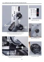


MAIN ASSEMBLY
10
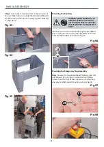
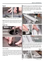
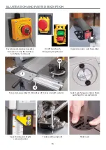
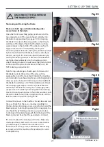
Step 2 Remove the table insert and table alignment pin
and place safely aside, see figs 16-17. Lift the table (1),
slide the blade through the table slot, see fig 18, line
up the two threaded bolts to the underside of the table
and lower them through the holes in the tilt quadrant
assembly, see fig 19.
Make sure the table is seated correctly on the tilt
quadrant then screw on the two clamping knobs (18)
to clamp the table (1) in position, see fig 20.
Fig 16-17
Fig 18
Fig 19
Fig 20
Table insert
Alignment pin
1
Threaded bolt
Tilt quadrant holes
18
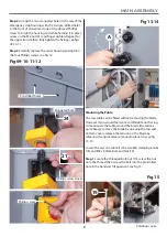
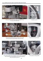
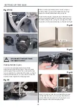
Step 3 Place a 90˚ square up against the blade, loosen
the tilt quadrant clamping handles (18) and adjust the
table levelling stop bolt (19) beneath the table until the
table is perpendicular to the blade. Nip tighten the nut
on the stop to lock the setting, see figs 21-22. Retight
the clamping knobs (18).
Fig 21-22
90˚ Square
19
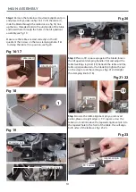
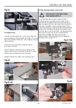
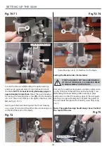
Step 4 Locate the table alignment pin you removed
earlier, place a straight edge or 90˚ square across the
table’s slot and introduce the tapered alignment pin into
the tapered hole to the front of the table, this will align
both sides of the table, see figs 23-24.
Fig 23
90˚ Square
Alignment pin
Содержание 107659
Страница 1: ...AP2552B Bandsaw Code 107659 AT 12 05 2022 BOOK VERSION 07 ...
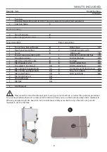
Страница 4: ...4 5 6 7 WHAT S INCLUDED 4 2 2 3 ...
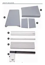
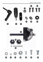
Страница 5: ...WHAT S INCLUDED 5 10 9 8 15 14 13 12 11 16 17 18 19 20 21 22 23 24 25 26 ...
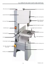
Страница 29: ...EXPLODED DIAGRAMS LISTS 29 Continues over Main Saw Assembly ...
Страница 35: ...WIRING DIAGRAM 35 ...