background image

AXIS Q7920 Chassis

4

Fan LED 1–2

5

Power supply 1–2 (PSU 1 and PSU 2)

6

Slot 1

7

Front panel cover

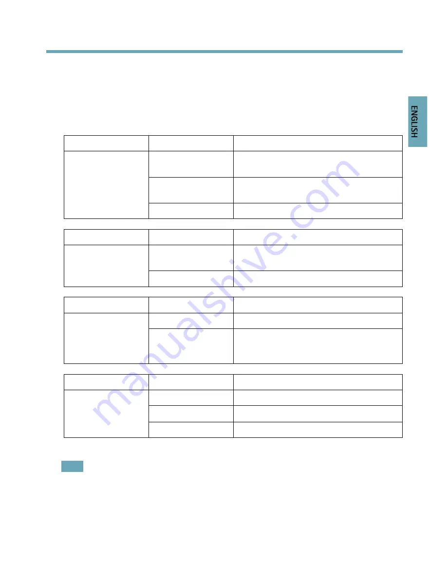
LED indicators

LED

Color

Indication

Green

Steady for a connection to 1000 Mbit/s
network. Flashes for network activity.

Amber

steady for a connection to 10/100 Mbit/s
network. Flashes for network activity.

Network RJ45 1–4

Unlit

No network connection.

LED

Color

Indication

Green

Steady for a connection to 1000 Mbit/s
network. Flashes for network activity.

Network SFP 1–4

Unlit

No network connection.

LED

Color

Indication

Green

PSU1 and PSU2 are connected and turned on.

PSU 1–2

Red

Indicates a fault in PSU1 or PSU2. It also
indicates if PSU1 or PSU2 are disconnected or
turned off.

LED

Color

Indication

Green

Both fans are working.

Flashes green/red

Indicates a fault in one fan.

Fan LED 1–2

Red

Indicates faults in both fans.

Note

In case of a faulty power supply, replace it with a new one. See

Replacing a power supply,

on page 14

In case of a faulty fan replace the fan tray with a new one. See

Replacing a fan tray,

on page 14

9

E

N

G

L

IS

H

Содержание Q7920

Страница 1: ...INSTALLATION GUIDE AXIS Q7920 Chassis ENGLISH...

Страница 2: ...ly visit Axis Support at www axis com techsup Learn More Visit Axis learning center www axis com academy for useful trainings webinars tutorials and guides Regulatory Information Europe This product c...

Страница 3: ...your nearest designated collection point contact your local authority responsible for waste disposal In accordance with local legislation penalties may be applicable for incorrect disposal of this wa...

Страница 4: ......

Страница 5: ...azardous situation which if not avoided could result in death or serious injury CAUTION Indicates a hazardous situation which if not avoided could result in minor or moderate injury NOTICE NOTICE NOTI...

Страница 6: ...es or walls Use only applicable tools when installing the Axis product Excessive force could cause damage to the product Do not use chemicals caustic agents or aerosol cleaners Use a damp cloth for cl...

Страница 7: ...the hardware overview See page 8 3 Install the hardware See page 10 Package Contents Video encoder chassis AXIS Q7920 Cover plates 1 1 port front panel cover 6 2 port front panel covers 2 AC power co...

Страница 8: ...4 RJ45 2 Network port 1 4 SFP 3 Fan tray cover 4 Grounding screw 5 I O terminal connector 6 RS 485 connector 7 Power in out connector Note SFP modules are not included in the delivery of AXIS Q7920 1...

Страница 9: ...etwork Flashes for network activity Network SFP 1 4 Unlit No network connection LED Color Indication Green PSU1 and PSU2 are connected and turned on PSU 1 2 Red Indicates a fault in PSU1 or PSU2 It al...

Страница 10: ...free space on the bottom front rear and on both sides of the AXIS Q7920 to ensure adequate ventilation Do not stack other units or objects directly on top of the AXIS Q7920 The mounting brackets are...

Страница 11: ...to right There are 4 slot groups in AXIS Q7920 Slot 1 4 slot 5 7 slot 8 11 and slot 11 14 The first blade should be inserted in slot 1 After that all slots can be used without any further regulations...

Страница 12: ...tors Provides the physical interface for up to 12 I Os Chassis ID Chassis ID 0 15 Sets a chassis ID Used in multichassis installations Chassis ID A P Currently not used Pin assignments Pin Assignments...

Страница 13: ...8 Channel 2 Configurable I O 2 9 Channel 3 Configurable I O 2 10 Channel 4 Configurable I O 2 11 Channel 5 Configurable I O 2 12 Channel 6 Configurable I O 2 Digital input Connect to GND to activate...

Страница 14: ...w located on the left side of the power supply and remove the power supply using the handle 3 Insert a new power supply and retighten the screw The AXIS Q7920 supports hot swap of a PSU A PSU can be r...

Страница 15: ...firmware version The upgrade may take up to one minute to accomplish Network Redundancy The network redundancy in AXIS Q7920 is controlled by software and requires that at least two network connectors...

Страница 16: ...nnection between slot groups and uplink groups Slot group 1 Slot 1 4 Uplink group 1 Slot group 2 Slot 5 7 Uplink group 2 Slot group 3 Slot 8 10 Uplink group 3 Slot group 4 Slot 11 14 Uplink group 4 Th...

Страница 17: ...AXIS Q7920 Chassis Warranty Information For information about Axis product warranty and thereto related information see www axis com warranty 17 ENGLISH...

Страница 18: ...Installation Guide Ver M1 13 AXIS Q7920 Chassis Date June 2013 Axis Communications AB 2013 Part No 51772...

Отзывы: