background image

Machine  Vision  MIRU130  Board 

Board  and  Pin  Assignments


11


2.4 

Connectors 

 
Signals  go  to  other  parts  of  the  system  through  connectors.  Loose  or  improper  connection 
might  cause  problems,  please  make  sure  all  connectors  are  properly  and  firmly  connected. 
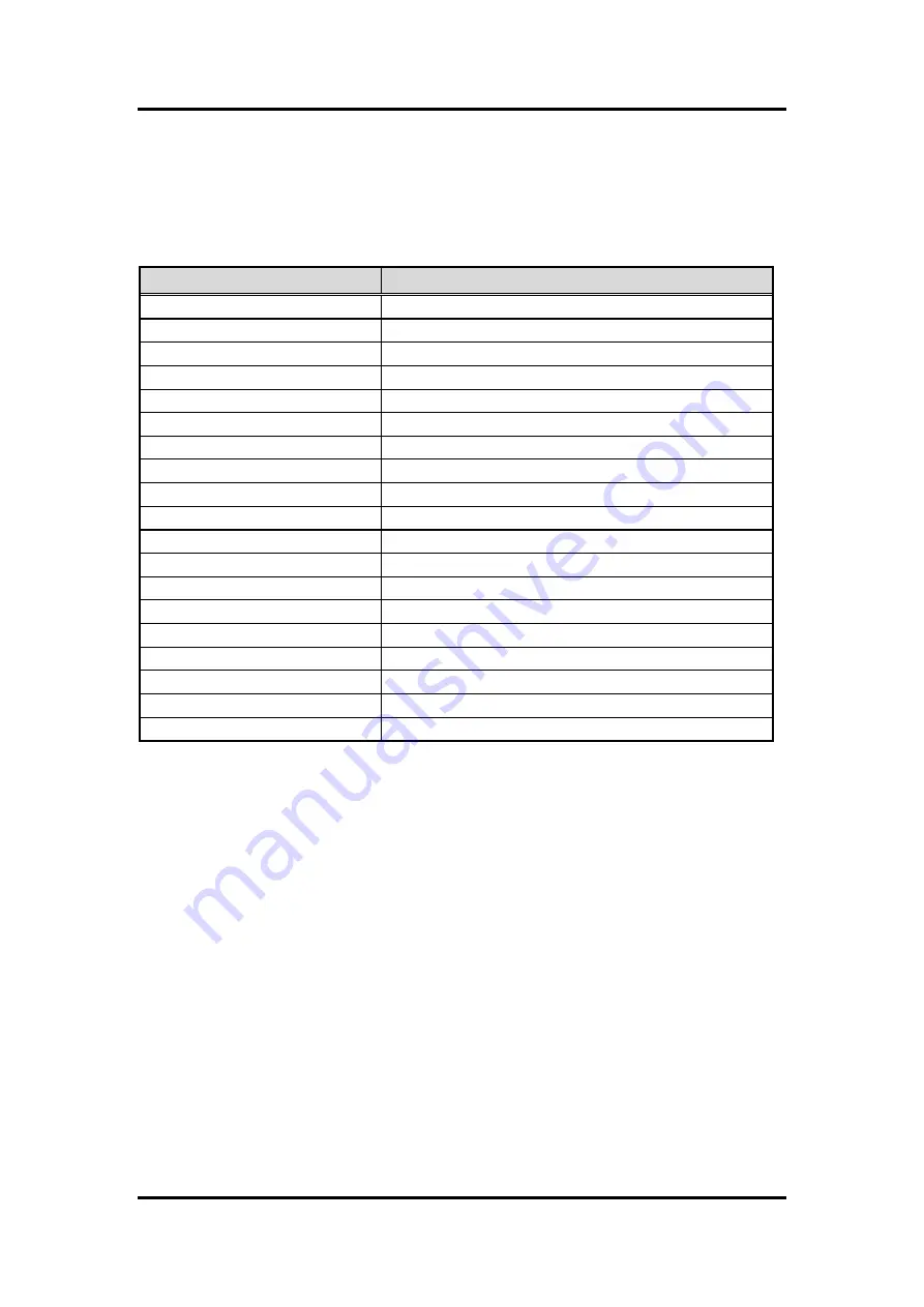
Here is a summary table of connectors on the hardware. 
 

Connector 

Description 

CN1 

TPM Wafer Connector 

CN2, CN6 

Fan Connectors 

CN3, CN4, CN7, CN8 

COM Wafer Connectors 

CN10 

Front Panel Connector 

CN11 

M.2 2230 Key E Connector 

CN12 

LED Lighting Control Wafer Connector 

CN13 

SIM Card Wafer Connector 

CN14 

Encoder Wafer Connector 

CN15 

PoE-PSE Port 

CN16, CN17 

Ethernet and USB 3.1 Ports 

CN18 

DisplayPort and HDMI Connector 

CN19 

Digital I/O Connector 

ATX2 

ATX Power Connector 

BAT1 

CMOS Battery Connector 

SATA1 

SATA Connector 

SATAP1 

SATA Power Connector 

SCN1 

M.2 Key B Connector 

GF1 

PCI-Express x16 Golden Finger 

DIMM1, DIMM2 

DDR4 SO-DIMM Connectors 


Содержание MIRU130

Страница 1: ...MIRU130 Machine Vision SBC with AMD RYZENTM Embedded V1605B V1807B User s Manual ...

Страница 2: ...anual Axiomtek reserves the right to change or revise this document and or product at any time without notice No part of this document may be reproduced stored in a retrieval system or transmitted in any form or by any means electronic mechanical photocopying recording or otherwise without the prior written permission of Axiomtek Co Ltd CAUTION If you replace wrong batteries it causes the danger o...

Страница 3: ...e system unit chassis for a few seconds It discharges static electricity from your body Wear a wrist grounding strap available from most electronic component stores when handling boards and components Trademarks Acknowledgments Axiomtek is a trademark of Axiomtek Co Ltd Intel and Celeron are trademarks of Intel Corporation Windows is a trademark of Microsoft Corporation AMI is a trademark of Ameri...

Страница 4: ... 13 2 4 4 Front Panel Connector CN10 14 2 4 5 M 2 2230 Key E Connector CN11 15 2 4 6 LED Lighting Control Wafer Connector CN12 16 2 4 7 SIM Card Wafer Connector CN13 16 2 4 8 Encoder Wafer Connector CN14 16 2 4 9 PoE PSE Port CN15 17 2 4 10 Ethernet and USB 3 1 Ports CN16 and CN17 17 2 4 11 DisplayPort and HDMI Connector CN18 18 2 4 12 Digital I O Connector CN19 19 2 4 13 ATX Power Connector ATX2 ...

Страница 5: ...4 Interrupt 31 Chapter 5 Hardware Description 33 5 1 Microprocessors 33 5 2 BIOS 33 5 3 System Memory 33 5 4 I O Port Address Map 34 5 5 Interrupt Controller IRQ Map 35 5 6 Memory Map 40 Chapter 6 AMI BIOS Setup Utility 41 6 1 Starting 41 6 2 Navigation Keys 41 6 3 Main Menu 43 6 4 Advanced Menu 44 6 5 Chipset Menu 56 6 6 Security Menu 60 6 7 Boot Menu 61 6 8 Save Exit Menu 63 Appendix A Watchdog ...

Страница 6: ...vi This page is intentionally left blank ...

Страница 7: ...R4 2400 3200MHz memory with maximum capacity up to 16GB There are two Gigabit Fast Ethernet ports two Gigabit PoE PSE ports one SATA port with transfer rate up to 6Gb s four USB 3 1 Gen 2 super speed compliant two isolated digital in and two isolated digital out that can achieve the best stability and reliability for industrial applications Additionally it provides you with unique embedded feature...

Страница 8: ...I Plug and Play PXE Ethernet Boot ROM System Memory Two 260 pin unbuffered DDR4 SO DIMM sockets For V1605B maximum up to 8GB DDR4 2400MHz memory for single SO DIMM socket Total up to 16GB For V1807B maximum up to 8GB DDR4 3200MHz memory for single SO DIMM socket Total up to 16GB Onboard Multi I O Controller Fintek F81803 Four serial ports COM1 supports RS 232 422 485 by BIOS selecting COM2 4 suppo...

Страница 9: ...ital I O Two isolated digital in Two isolated digital out Two isolated trigger in Two isolated trigger out for camera Vision I O Two CH LED lighting control output supporting dimming control One CH incremental quadrature encoder input A B Z Expansion Interface One M 2 Key E connector in 2230 Power Input One 2x4 pin connector 12V DC in only AT auto power on function supported Power Management ACPI ...

Страница 10: ...Machine Vision MIRU130 Board 4 Introduction This page is intentionally left blank ...

Страница 11: ...Machine Vision MIRU130 Board Board and Pin Assignments 5 Chapter 2 Board and Pin Assignments 2 1 Board Dimensions and Fixing Holes Top View ...

Страница 12: ...Machine Vision MIRU130 Board 6 Board and Pin Assignments Bottom View Side View ...

Страница 13: ...Machine Vision MIRU130 Board Board and Pin Assignments 7 2 2 Board Layout Top View ...

Страница 14: ...Machine Vision MIRU130 Board 8 Board and Pin Assignments Bottom View ...

Страница 15: ...nd a summary table of all switches and onboard default settings Note Once the default switch setting needs to be changed please do it under power off condition Switch Description Setting SW1 Auto Power On Default Enable SW1 1 ON Restore BIOS Optimal Defaults Default Normal Operation SW1 2 OFF SW3 LED Lighting Control Output Current Setting Default 100mA SW3 1 ON SW4 SW4 1 ON ...

Страница 16: ...storing BIOS default status Flip SW1 2 to ON position for a few seconds then flip it back to OFF position Doing this procedure can restore BIOS optimal defaults 2 3 2 LED Lighting Control Output Current Setting SW3 and SW4 Use SW3 and SW4 to choose different LED lighting control output current Function Setting Enable auto power on Default SW1 1 ON Disable auto power on SW1 1 OFF Restore BIOS optim...

Страница 17: ...onnector CN2 CN6 Fan Connectors CN3 CN4 CN7 CN8 COM Wafer Connectors CN10 Front Panel Connector CN11 M 2 2230 Key E Connector CN12 LED Lighting Control Wafer Connector CN13 SIM Card Wafer Connector CN14 Encoder Wafer Connector CN15 PoE PSE Port CN16 CN17 Ethernet and USB 3 1 Ports CN18 DisplayPort and HDMI Connector CN19 Digital I O Connector ATX2 ATX Power Connector BAT1 CMOS Battery Connector SA...

Страница 18: ... are needed for cooling down CPU and system temperature The board has two fan connectors You can find fan speed within BIOS Setup Utility if fan is installed For further information see BIOS Setup Utility Advanced Hardware Monitor see section 6 4 CN2 for system fan 1 CN6 for CPU fan Pin Signal 1 VCC 2 SPI_TPM_MISO 3 SPI_TPM_CLK 4 SPI_TPM_MOSI 5 SPI_TPM_CS_N 6 SPI_TPM_IRQ 7 PLTRST_N 8 GND Pin Signa...

Страница 19: ...f you need COM1 to support RS 422 or RS 485 communication mode please refer to BIOS setting in section 6 4 Option cable 59380880250E COM Port Cable DB9 9x1P L250mm P 1 25 CN3 CN4 and CN7 for COM2 COM3 and COM4 CN8 for COM1 Pin RS 232 1 DCD 2 DSR 3 RXD 4 RTS 5 TXD 6 CTS 7 DTR 8 RI 9 GND Pin RS 232 RS 422 RS 485 1 DCD TX Data 2 DSR No use No use 3 RXD TX Data 4 RTS No use No use 5 TXD RX No use 6 CT...

Страница 20: ...power button on front panel to CPU board which allows users to turn on or off power supply System Reset Switch Pin 10 and 9 connect the case mounted reset switch that reboots your computer without turning off the power switch It is a better way to reboot your system for a longer life of system power supply HDD Activity LED This connection is linked to hard drive activity LED on the control panel L...

Страница 21: ...15 NC 16 NC 17 NC 18 GND 19 NC 20 NC 21 NC 22 NC 23 NC 24 Key E 25 Key E 26 27 28 29 30 31 32 NC 33 GND 34 NC 35 PCIE3_TX_P 36 NC 37 PCIE3_TX_N 38 NC 39 GND 40 NC 41 PCIE3_RX_P 42 NC 43 PCIE3_RX_N 44 NC 45 GND 46 NC 47 CLK_PCIE3_P 48 NC 49 CLK_PCIE3_N 50 SUSCLK 3 3V Level 51 GND 52 PERST 3 3V Level 53 CLKREQ0 54 W_DIS2 3 3V Level 55 PEWAKE0 56 W_DI12 3 3V Level 57 GND 58 SMB_DATA 3 3V Level 59 NC ...

Страница 22: ... SIM Card Wafer Connector CN13 The CN13 is a 6 pin pitch 1 0mm wafer connector which is compliant with JST SHR 06V SB for SIM Card interface It is suggested to connect AX93A19 to have a SIM card slot 2 4 8 Encoder Wafer Connector CN14 This is a 2x6 pin pitch 2 0mm wafer connector which is compliant with JST PHDR 12VS for one CH incremental quadrature encoder input A B Z Option cable 594L1303500E D...

Страница 23: ...ional or Transmit Data L2 BI_DA TX Bidirectional or Transmit Data L3 BI_DB RX Bidirectional or Receive Data L4 BI_DC N C Bidirectional or Not Connected L5 BI_DC N C Bidirectional or Not Connected L6 BI_DB RX Bidirectional or Receive Data L7 BI_DD N C Bidirectional or Not Connected L8 BI_DD N C Bidirectional or Not Connected A Speed LED 1000 Orange 100 10 Green OFF B Active Link LED Yellow Off No l...

Страница 24: ... USB 1_D 4 GND 13 GND 5 SSRX0 14 SSRX1 6 SSRX0 15 SSRX1 7 GND 16 GND 8 SSTX0 17 SSTX1 9 SSTX0 18 SSTX1 Pin DP Signal Pin HDMI Signal 1 LANE 0 21 DATA2 2 GND 22 GND 3 LANE 0 23 DATA2 4 LANE 1 24 DATA1 5 GND 25 GND 6 LANE 1 26 DATA1 7 LANE 2 27 DATA0 8 GND 28 GND 9 LANE 2 29 DATA1 10 LANE 3 30 Clock 11 GND 31 GND 12 LANE 3 32 Clock 13 Detect Pin 33 NC 14 GND 34 NC 15 AUX CH 35 SCL 16 GND 36 SDA 17 A...

Страница 25: ...r Please make sure all components and devices are properly installed before connecting the power connector The ATX2 is an 2x4 pin power input interface Follow the connector orientation to plug the external power supply Properly press down power supply plug until it completely and firmly fits into this connector Loose connection may cause system instability 2 4 14 CMOS Battery Connector BAT1 This c...

Страница 26: ...high speed SATA interface It is a computer bus interface for connecting to devices such as hard disk drive 1 7 2 4 16 SATA Power Connector SATAP1 This is a 4 pin pitch 2mm wafer connector which is compliant with JST B4B PH K S for SATA power interface Pin Signal 1 GND 2 SATA_TXP0 3 SATA_TXN0 4 GND 5 SATA_RXN0 6 SATA_RXP0 7 GND Pin Signal 1 12V 2 GND 3 GND 4 5V 1 4 ...

Страница 27: ...D 12 Key B 13 Key B 14 15 16 17 18 19 20 NC 21 CONFIG_0 22 NC 23 GPIO11 1 8V 24 NC 25 NC 26 NC 27 GND 28 NC 29 USB3 0 RX PERn1 option 30 SIM_RST 31 USB3 0 RX PERp1 option 32 SIM_CLK 33 GND 34 SIM_DATA 35 USB3 0 TX PETn1 option 36 SIM_PWR 37 USB3 0 TX PETn1 option 38 NC 39 GND 40 SMB_CLK_SBY 1 8V 41 SATA1_RX_P PERn0 option 42 SMB_DATA_SBY 1 8V 43 SATA1_RX_N PERp0 option 44 NC 45 GND 46 NC 47 SATA1_...

Страница 28: ...V B10 3 3VAUX A11 PWRGD B11 WAKE_N A12 GND B12 NC A13 REFCLK B13 GND A14 REFCLK B14 HSOP_0 A15 GND B15 HSON_0 A16 HSIP_0 B16 GND A17 HSIN_0 B17 PRSNT2 A18 GND B18 GND A19 NC B19 HSOP_1 A20 GND B20 HSON_1 A21 HSIP_1 B21 GND A22 HSIN_1 B22 GND A23 GND B23 HSOP_2 A24 GND B24 HSON_2 A25 HSIP_2 B25 GND A26 HSIN_2 B26 GND A27 GND B27 HSOP_3 A28 GND B28 HSON_3 A29 HSIP_3 B29 GND A30 HSIN_3 B30 NC A31 GND...

Страница 29: ...52 NC B52 GND A53 NC B53 GND A54 GND B54 NC A55 GND B55 NC A56 NC B56 GND A57 NC B57 GND A58 GND B58 NC A59 GND B59 NC A60 NC B60 GND A61 NC B61 GND A62 GND B62 NC A63 GND B63 NC A64 NC B64 GND A65 NC B65 GND A66 GND B66 NC A67 GND B67 NC A68 NC B68 GND A69 NC B69 GND A70 GND B70 NC A71 GND B71 NC A72 NC B72 GND A73 NC B73 GND A74 GND B74 NC A75 GND B75 NC A76 NC B76 GND A77 NC B77 GND A78 GND B78...

Страница 30: ... Up DIMM1 DIMM2 Install the memory module s into DIMM1 or DIMM2 carefully as indicated in image below First follow arrow 1 insert memory module at approximately 15 degree angle into the socket Then push module in the direction of arrow 2 until it completely fits into DIMM1 or DIMM2 ...

Страница 31: ... the MIRU130 and device Each of the following I O figures illustrates their respective connection on the MIRU130 3 1 1 Isolated Digital Input The following figure shows how to connect between external input source and the MIRU130 Dry contact Wet contact Each of the isolated digital input channels accepts 0 30VDC with sink type and source type ...

Страница 32: ...age 5 30VDC is applied to an isolated output channel the current will flow from the external voltage source to the board Please note that the current through each DO channel should not exceed 200mA Resister load Inductive load 3 1 3 Isolated Trigger Input and Auto Measurement Input The following figure shows how to connect between external input source and the MIRU130 Dry contact ...

Страница 33: ...ith sink type 3 1 4 Isolated Trigger Output The following figure shows how to connect between an output channel and the MIRU130 The board provides voltage 12VDC for an isolated output channel 3 1 5 Isolated Encoder Input The following figure shows how to connect between an input channel and the MIRU130 Differential type ...

Страница 34: ...Machine Vision MIRU130 Board 28 I O Connection 5V Voltage Type ...

Страница 35: ...otor movement by comparing the phase relationship between Phase A and B When the quadrature encoder is rotating in a clockwise direction its signal will show a positive direction of Phase A leading Phase B When the quadrature encoder rotates counterclockwise its signal will show a negative direction of Phase A lagging behind Phase B Besides direction the quadrature encoder can generate another sig...

Страница 36: ... 2ms 2ms 2ms 2ms 2ms Trigger Output CH 0 1 provides the following parameters to configure Trigger source The user can select any of the following items as a triggering condition that prompts the MIRU130 to generate a trigger output Trigger Input CH 0 3 Encoder Phase Z Encoder Check Pointer CH0 2 Note One trigger source can be set to activate multiple trigger outputs Delay time function The user ca...

Страница 37: ...ings for various machine vision applications Note The MIRU130 card provides the power sources as below Output voltage 24VDC max 0 5A per channel Each channel can be set to provide 100mA 250mA 350mA 500mA output by switch 4 1 4 Interrupt This function can send an interrupt signal to the host PC The user can select two conditions from the list below for the MIRU130 to generate an interrupt signal 1 ...

Страница 38: ...Machine Vision MIRU130 Board 32 Operating This page is intentionally left blank ...

Страница 39: ...ws 10 environments The system performance depends on the microprocessor Make sure all correct settings are arranged for the installed microprocessor to prevent the CPU from damages 5 2 BIOS The MIRU130 uses AMI Plug and Play BIOS with a single 64Mbit SPI Flash 5 3 System Memory The MIRU130 supports two 260 pin DDR4 SO DIMM sockets The memory module comes in sizes of 2GB 4GB and 8GB ...

Страница 40: ...Machine Vision MIRU130 Board 34 Hardware Description 5 4 I O Port Address Map ...

Страница 41: ...Machine Vision MIRU130 Board Hardware Description 35 5 5 Interrupt Controller IRQ Map The interrupt controller IRQ mapping list is shown as follows ...

Страница 42: ...Machine Vision MIRU130 Board 36 Hardware Description ...

Страница 43: ...Machine Vision MIRU130 Board Hardware Description 37 ...

Страница 44: ...Machine Vision MIRU130 Board 38 Hardware Description ...

Страница 45: ...Machine Vision MIRU130 Board Hardware Description 39 ...

Страница 46: ...Machine Vision MIRU130 Board 40 Hardware Description 5 6 Memory Map The memory mapping list is shown as follows ...

Страница 47: ...up menu displays You can access the other setup screens from the main BIOS setup menu such as the Advanced and Chipset menus Note If your computer cannot boot after making and saving system changes with BIOS setup you can restore BIOS optimal defaults by setting SW1 2 see section 2 4 1 It is strongly recommended that you should avoid changing the chipset s defaults Both AMI and your system manufac...

Страница 48: ... F1 The F1 key allows you to display the General Help screen F2 The F2 key allows you to Load Previous Values F3 The F3 key allows you to Load Optimized Defaults F4 The F4 key allows you to save any changes you have made and exit Setup Press the F4 key to save your changes Esc The Esc key allows you to discard any changes you have made and exit the Setup Press the Esc key to exit the setup without...

Страница 49: ...cribed below The Main BIOS setup screen is shown below BIOS Information Display BIOS information System Date Time Use this option to change the system time and date Highlight System Time or System Date using the Arrow keys Enter new values through the keyboard Press the Tab key or the Arrow keys to move between fields The date must be entered in MM DD YY format The time is entered in HH MM SS form...

Страница 50: ...CPU and other system devices You can select any of the items in the left frame of the screen to go to the sub menus IT8786 Super IO Configuration Hardware Monitor ACPI Settings Trusted Computing CPU Configuration SATA Configuration USB Configuration Serial Port Console Redirection For items marked with please press Enter for more options ...

Страница 51: ... select options for serial port configuration and change the value of the selected option A description of the selected item appears on the right side of the screen For items marked with please press Enter for more options Serial Port 1 4 Configuration Use these items to set parameters related to serial port 1 4 ...

Страница 52: ... Enable or disable serial port 1 The optimal setting for base I O address is 3F8h and for interrupt request address is IRQ4 COM Port Type Use this item to set RS 232 422 485 communication mode Terminal Mode Enable terminal mode to enable the RS 422 485 termination resistor to enhance the signal ...

Страница 53: ...optimal setting for base I O address is 2F8h and for interrupt request address is IRQ3 Enable or disable serial port 3 The optimal setting for base I O address is 3E8h and for interrupt request address is IRQ11 Enable or disable serial port 4 The optimal setting for base I O address is 2E8h and for interrupt request address is IRQ10 ...

Страница 54: ...ty Hardware Monitor This screen monitors hardware health status This screen displays the temperature of system and CPU fan speed in RPM and system voltages Smart Fan Function Use this item to set Smart Fan function CPU Fan Setting and System Fan Setting ...

Страница 55: ...se System Temperature1 System Temperature2 or CPU Temperature Fan off temperature limit The fan will off when temperature is lower than this limit Fan start temperature limit The fan will work when temperature is higher than this limit Fan full speed temperature limit The fan will run in full speed when temperature is higher than this limit Fan start PWM The fan will start with this PWM value and ...

Страница 56: ... value and its range is from 0 to 255 see image below ACPI Settings ACPI Sleep State Select the ACPI Advanced Configuration and Power Interface sleep state Configuration options are Suspend Disabled and S3 Suspend to RAM When S3 Suspend to RAM option is selected the system will enter after suspend button is pressed ...

Страница 57: ...MI BIOS Setup Utility 51 Trusted Computing You can use this screen for TPM Trusted Platform Module configuration It also shows current TPM status information Security Device Support Enable or disable BIOS support for security device ...

Страница 58: ...n This screen shows the CPU Configuration SVM Mode Enable or disable SVM Secure Virtual Machine mode Once enabled you will be able to install a virtual machine on your system Core Performance Boost If enabled the CPU can be boosted up to its maximum clock speed when needed ...

Страница 59: ... 53 SATA Configuration During system boot up BIOS automatically detects the presence of SATA devices In the SATA Configuration menu you can see the hardware currently installed in SATA ports USB Configuration USB Devices Display all detected USB devices ...

Страница 60: ...ght side of the screen For items marked with please press Enter for more options COM1 COM2 COM3 COM4 Console Redirection Enable or disable COM1 COM2 COM3 COM4 console redirection Once it is enabled you will see the following screen COM1 COM2 COM3 COM4 Console Redirection Settings When enabled the settings specify how the host computer and the remote computer which the user is using will exchange d...

Страница 61: ...Machine Vision MIRU130 Board AMI BIOS Setup Utility 55 Console Redirection Settings ...

Страница 62: ...6 5 Chipset Menu The Chipset menu allows users to change the advanced chipset settings You can select any of the items in the left frame of the screen to go to the sub menus North Bridge South Bridge For items marked with please press Enter for more options ...

Страница 63: ...S Setup Utility 57 North Bridge This screen displays system memory information And it also allows users to configure parameters of North Bridge chipset Graphics Configuration Open sub menu for parameters related to graphics configuration ...

Страница 64: ...ard 58 AMI BIOS Setup Utility Primary Video Adaptor Select Internal CN18 see section 2 4 11 or External the graphic card on GF1 see section 2 4 18 Graphics as primary display IGD UMA Frame Size Set memory frame size for graphic ...

Страница 65: ...Machine Vision MIRU130 Board AMI BIOS Setup Utility 59 South Bridge This screen shows the AMD Reference Code Version information ...

Страница 66: ...MIRU130 Board 60 AMI BIOS Setup Utility 6 6 Security Menu The Security menu allows users to change the security settings for the system Administrator Password Set administrator password User Password Set user password ...

Страница 67: ... options of the system Setup Prompt Timeout Number of seconds to wait for setup activation key 65535 0xFFFF means indefinite waiting Bootup NumLock State Use this item to select the power on state for the keyboard NumLock Quiet Boot Select to display either POST output messages or a splash screen during boot up ...

Страница 68: ...h LAN device will enable PXE OpROM policy Boot Option Priorities Boot Option 1 These are settings for boot priority Specify the boot device priority sequence from the available devices USB Device Hard Drive BBS Priorities Set the boot order of the specific devices in this group This option appears only if at least one device of this group is detected ...

Страница 69: ...it menu and press Enter Select Yes to discard changes and exit Save Changes and Reset When you have completed the system configuration changes select this option to leave Setup and reboot the computer so the new system configuration parameters can take effect Select Save Changes and Reset from the Save Exit menu and press Enter Select Yes to save changes and reset Discard Changes and Reset Select ...

Страница 70: ...when you select this option Select Restore Defaults from the Save Exit menu and press Enter Save as User Defaults Select this option to save system configuration changes done so far as User Defaults Select Save as User Defaults from the Save Exit menu and press Enter Restore User Defaults It automatically sets all Setup options to a complete set of User Defaults when you select this option Select ...

Страница 71: ...alue and must reset it periodically If the counter ever reaches zero which means the software has crashed the system will reboot A 2 How to Use Watchdog Timer The I O port base addresses of watchdog timer are 2E hex and 2F hex The 2E hex and 2F hex are address and data port respectively Assume that program A is put in a loop that must execute at least once every 10ms Initialize watchdog timer with...

Страница 72: ...3 define SIO_Countdown_Type_Second 0xC0 define SIO_Countdown_Type_Minute 0x40 define SIO_Exit_Configuration_Mode 0x02 void main int CountdownType 0 int WDTtimer 0 printf Input Watch Dog Timer type 1 Second 2 Minute scanf d CountdownType printf nInput Timer to countdown scanf d WDTtimer printf Start to countdown Enter Configuration Mode outportw SIO_Index_Port 0x87 outportw SIO_Index_Port SIO_Enter...

Страница 73: ...down_Type if CountdownType 1 outportw SIO_Data_Port SIO_Countdown_Type_Second else if CountdownType 2 outportw SIO_Data_Port SIO_Countdown_Type_Minute Set WDT Timer outportw SIO_Index_Port SIO_Offset_Countdown_Timer outportw SIO_Data_Port WDTtimer Exit Configuration Mode outportw SIO_Index_Port SIO_Exit_Configuration_Mode outportw SIO_Index_Port SIO_Exit_Configuration_Mode ...

Отзывы: