background image

IPC912 Series User’s Manual 

AMI BIOS 

Utility


48 

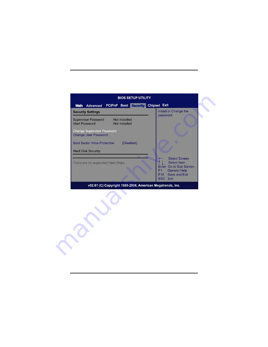
3.7   Security Menu 

The Security menu allows users to change the security settings for the 
system.  


¾


Supervisor Password 

This item indicates whether a supervisor password has 
been set. If the password has been installed, Installed 
displays. If not, Not Installed displays. 

¾


User Password 

This item indicates whether a user password has been set. 
If the password has been installed, Installed displays. If not, 
Not Installed displays. 

¾


Change Supervisor Password 

Select this option and press <Enter> to access the sub 
menu. You can use the sub menu to change the supervisor 
password.

Содержание IPC912 Series

Страница 1: ...IPC912 Series Industrial Fanless Computers User s Manual...

Страница 2: ...ompleteness or usefulness of any information in this document Axiomtek does not make any commitment to update the information in this manual Axiomtek reserves the right to change or revise this docume...

Страница 3: ...grounded 4 Make sure the voltage of the power source is correct before connecting the equipment to the power outlet 5 Turn OFF the system power before cleaning Clean the system using a cloth only Do...

Страница 4: ...acuum cleaner to absorb the dirt on the floor 2 Turn the system off before you start to clean up the component or computer 3 Never drop the components inside the computer or get circuit board damp or...

Страница 5: ...icles out of a computer can be one of the best methods of cleaning a computer Over time these items can restrict the airflow in a computer and cause circuitry to corrode z Cotton swabs Cotton swaps mo...

Страница 6: ...ct your Axiomtek distributor for recycling and we will make the proper arrangement Trademarks Acknowledgments Axiomtek is a trademark of Axiomtek Co Ltd IBM PC AT PS 2 VGA are trademarks of Internatio...

Страница 7: ...ard 3 1 2 2 I O System 3 1 2 3 System Specification 4 1 3 Dimensions 5 1 4 I O Outlets 6 1 5 Jumper Settings 7 1 6 Packing List 12 CHAPTER 2 13 HARDWARE INSTALLATION 13 2 1 Installing the Processor 13...

Страница 8: ...IPC912 Series User s Manual viii 3 6 Boot Menu 45 3 7 Security Menu 48 3 8 EXIT Menu 54 Appendix A 56 CAN BUS Module Introduce 56...

Страница 9: ...IPC912 Series User s Manual ix MEMO...

Страница 10: ......

Страница 11: ...on 1 CHAPTER 1 INTRODUCTION This chapter contains general information and a detailed specification of the IPC912 Series Chapter 1 includes the following sections General Description System Specificati...

Страница 12: ...st endurable operation Reliable and Stable Design The IPC912 Series adopts two anti vibration hard drive bays which makes it especially suitable for vibration environments best for industrial automati...

Страница 13: ...MHz SODIMM sockets with maximum up to 8GB z Features Fanless Operation Compact Front IO design Supports Two expansion slots DC to DC power supply support 10V to 30V 1 2 2 I O System z Standard I O Int...

Страница 14: ...8W 1 2 3 System Specification z Drive Capacity Supports One 2 5 HDD driver bay one onboard CompactFlash Socket z Power Input 10VDC to 30VDC with phoenix power plug External 150W AC Adapter Power Input...

Страница 15: ...IPC912 Series User s Manual Introduction 5 1 3 Dimensions The following diagrams show you dimensions and outlines of the IPC912 Series...

Страница 16: ...on front and rear panels of the IPC912 Series Front Panel 1 Ethernet x 2 2 VGA Port 3 USB 2 0 x 2 4 LED for Power HDD 5 ATX Power Switch 6 Power Connector Din Jack or Phoenix Plug 7 RS 232 COM2 3 4 R...

Страница 17: ...that allow you to configure your system to suit your application The table below lists the functions of the various jumpers These jumpers select the COM1 port s communication mode to operate RS 232 or...

Страница 18: ...Manual Introduction 8 These jumpers select the COM1 COM2 ports DCD and RI mode Description Function Jumper Setting Pin 1 12V Pin 1 5V Pin 1 DCD Default Pin 8 12V Pin 8 5V COM1 DCD RI Voltage Selection...

Страница 19: ...ntroduction 9 Description Function Jumper Setting Pin 1 12V Pin 1 5V Pin 1 DCD Default Pin 8 12V Pin 8 5V COM2 DCD RI Voltage Selection JP5 Pin 8 RI Default NOTE If you are using COM2 as a CAN Bus mod...

Страница 20: ...ctFlash Voltage Selection Jumper JP12 This jumper is to select the voltage for CompactFlashTM interface Description Function Jumper Setting 3 3V Default CompactFlash TM Voltage Selection 5V CMOS Clear...

Страница 21: ...This jumper is to select the voltage for USB interface Description Function Jumper Setting 5V USB Voltage Selection 5V_SBY LVDS Voltage Selection Jumper JP18 This jumper is to select the voltage for L...

Страница 22: ...ain the following items z IPC912 Series Unit x 1 z 19V 150W Adapter and US Power Cord for IPC912 AC Version z Driver CD z Quick Manual z Wall Mount Bracket x 2 z HD Bracket x 1 z Screw pack x 1 z Food...

Страница 23: ...w processor carefully review the documentation that came with your system and make sure that you will not be voiding your warranty by opening the computer or replacing your processor Instructions 1 Ma...

Страница 24: ...rent processor use a screwdriver to disengage open the socket actuator as shown in Figure 1 below The most commonly used sockets are Molex or FoxConn sockets so they are used in the illustrations belo...

Страница 25: ...eatsink as marked Align pins of the CPU with pin holes of the socket Be careful of the CPU s orientation that you need to align the arrow mark on the CPU with the arrow key on the socket Place the CPU...

Страница 26: ...IPC912 Series User s Manual Hardware Installation 16 Step 6 Close the top and side covers back to the chassis and fasten all screws...

Страница 27: ...e system Step 2 Disconnect the power connector Step 3 Loosen screws to remove the side cover from the chassis Step 4 Please follow steps below to install the upper memory module 1 Align the memory mod...

Страница 28: ...nstallation 18 2 Install the memory module into the socket and push it firmly down until it is fully seated The socket latches are clipped on to the edges of the SO DIMM Step 5 Put back the side cover...

Страница 29: ...bay module for users to install HDD The system offers users one 2 5 Hard Disk Drive for installation Please follow the steps Step 1 Turn off the system Step 2 Disconnect the power connector Step 3 Loo...

Страница 30: ...Hardware Installation 20 Step 5 Use assembly parts to fix HDD with the bracket Step 6 Install and fix the HDD through the side next plug the power cable in HDD Step 7 Close the top cover back to the c...

Страница 31: ...g the PCI or PCIe Card Step 1 Turn off the system Step 2 Disconnect the power connector Step 3 Loosen screws to remove the top cover from the chassis Removing the PCI or PCIe bracket by releasing the...

Страница 32: ...User s Manual Hardware Installation 22 Step 5 Align the PCI or PCIe card with the slot and press the card into the slot until it is firmly seated Step 6 Close the top cover back to the chassis and fas...

Страница 33: ...low you to select a setup screen Up Down The Up and Down Arrow keys allow you to select a setup screen or sub screen Plus Minus The Plus and Minus Arrow keys allow you to change the field value of a p...

Страница 34: ...our selection Use arrow keys to select the Setup Page you intend to configure then press Enter to accept or enter its sub menu z System Time Date Use this option to change the system time and date Hig...

Страница 35: ...s in the left frame of the screen to go to the sub menus y CPU Configuration y IDE Configuration y Floppy Configuration y SuperIO Configuration y Hardware Health Configuration y ACPI Configuration y A...

Страница 36: ...lity 26 z CPU Configuration This screen shows the CPU Configuration and you can change the value of the selected option this section allows you to configure and improve your system to set up some syst...

Страница 37: ...this item to select MPS Multi Processor Specification Revision 1 1 or 1 4 The default setting is 1 4 Hardware Prefetcher This item automatically analyzes its requirements and prefetches data and inst...

Страница 38: ...ting systems boot even without support for CPUs with extended CPU ID functions Intel R Virtualization Tech Use this feature to enable or disable the Intel Virtualization Technology IVT extensions whic...

Страница 39: ...s item to control the onboard SATA controller Here are the options for your selection Compatible Disabled and Enhanced Configure SATA 1 as Use this item to choose the SATA operation mode Here are the...

Страница 40: ...elect options for the Floppy Configuration and change the value of the selected option A description of the selected item appears on the right side of the screen For items marked with f please press E...

Страница 41: ...oard Floppy Controller Use this item to enable or disable the onboard floppy drive controller Serial Port1 Address This option specifies the base I O port address and Interrupt Request address of seri...

Страница 42: ...ity 32 Serial Port2 Mode This item specifies the mode used by the serial port 2 Parallel Port Address Select an operating mode for the onboard parallel printer port Parallel Port IRQ Use this item to...

Страница 43: ...ect this item Enabled for the Hardware Health Monitoring Device The Hardware Health Event Monitoring displays the temperature of CPU and System Fan Speed Vcore etc SYSFAN CPUFAN AUXFAN Mode Setting Th...

Страница 44: ...Configuration sub menu which contains General ACPI Advanced Configuration and Power Management Interface options for your configuration Advanced ACPI Configuration Scroll to this item and press Enter...

Страница 45: ...IPC912 Series User s Manual AMI BIOS Utility 35 Interface options for your configuration...

Страница 46: ...this screen to select options for the AHCI Configuration and change the value of the selected option A description of the selected item appears on the right side of the screen AHCI BIOS Support You ca...

Страница 47: ...the selected item appears on the right side of the screen Power Management Set this value to allow Power Management APM support The default setting is Enabled Disabled Set this value to prevent the ch...

Страница 48: ...ents the BIOS from initiating any power saving modes concerned with the video display or monitor Standby This option places the monitor into standby mode after the specified period of display inactivi...

Страница 49: ...pend This is the default setting Throttle Slow Clock Ratio Use this item to specify the speed of the system clock when running the power saving states System Thermal Use this item to enable or disable...

Страница 50: ...a description of the selected item appears on the right side of the screen View Event Log This item is to display the system events in the System Event Log Mark all events as read This item is to mar...

Страница 51: ...this screen to select options for the Smbios Configuration and change the value of the selected option A description of the selected item appears on the right side of the screen Smbios Smi Support Wh...

Страница 52: ...ation and change the value of the selected option A description of the selected item appears on the right side of the screen USB Functions This item allows you to enable or disable USB functions Legac...

Страница 53: ...item to configure all the devices in the system When the setting is Yes and if you install a Plug and Play operating system the operating system configures the Plug and Play devices not required for...

Страница 54: ...m DMA Direct Memory Access transfer Here are the options for your selection Disabled and Enabled OffBoard PCI ISA IDE Card This item is for any other non onboard PCI ISA IDE controller adapter There a...

Страница 55: ...Boot Menu The Boot menu allows users to change boot options of the system You can select any of the items in the left frame of the screen to go to the sub menus y Boot Settings Configuration For item...

Страница 56: ...or disable the Boot ROM function of the onboard LAN chip when the system boots up AddOn ROM Display Mode This item selects the display mode for option ROM The default setting is Force BIOS Boot Num L...

Страница 57: ...Display If this item is enabled the system displays the message Press DEL to run Setup during POST The default setting is Enabled Interrupt 19 Capture If this item is enabled this function makes the o...

Страница 58: ...password has been set If the password has been installed Installed displays If not Not Installed displays User Password This item indicates whether a user password has been set If the password has bee...

Страница 59: ...ault setting Enabled Select Enabled to enable boot sector protection It displays a warning when any program or virus issues a Disk Format command or attempts to write to the boot sector of the hard di...

Страница 60: ...ipset menu allows users to change the advanced chipset settings You can select any of the items in the left frame of the screen to go to the sub menus y North Bridge Configuration y South Bridge Confi...

Страница 61: ...ystem memory for the memory requirements Here are the options Disabled and 15M 16M Boot Graphic Adapter Priority This item allows you to select the graphics controller as the primary boot device Inter...

Страница 62: ...Configuration USB Controller This item allows you to enable or disable USB function controller Restore on AC Power Loss This item can control how the PC will behave once power is restored following a...

Страница 63: ...IPC912 Series User s Manual AMI BIOS Utility 53 outage or other unexpected shutdown...

Страница 64: ...Setup and reboot the computer so the new system configuration parameters can take effect Select Save Changes and Exit from the Exit menu and press Enter Select Ok to save changes and exit Discard Cha...

Страница 65: ...your computer is experiencing system configuration problems Select Load Optimal Defaults from the Exit menu and press Enter Load Fail Safe Defaults It automatically sets all Setup options to a complet...

Страница 66: ...IPC912 Series User s Manual Can Bus Module Introduce 56 Appendix A CAN BUS Module Introduce A 1 Board Layout...

Страница 67: ...IPC912 Series User s Manual Can Bus Module Introduce 57 A 2 Block Diagram...

Страница 68: ...IPC912 Series User s Manual Can Bus Module Introduce 58 A 3 Connector Pin Define COM1 PIN PIN Define 1 NC 2 CAN_L 3 CAN_GND 4 NC 5 NC 6 CAN_GND 7 CAN_H 8 NC 9 NC...

Страница 69: ...PIN Define USB PIN Define RS23 2 PI N PIN Defin e 1 5V 5V 2 NC 3 USB_D TXD 4 CTS 5 USB_D RXD 6 RTS 7 NC NC 8 NC 9 GND GND 10 GND Connection for CAN transmission NOTE To be sure there is at least one...

Отзывы: