background image

GOT-5120TL User

s Manual 


Hardware Installation 

19 

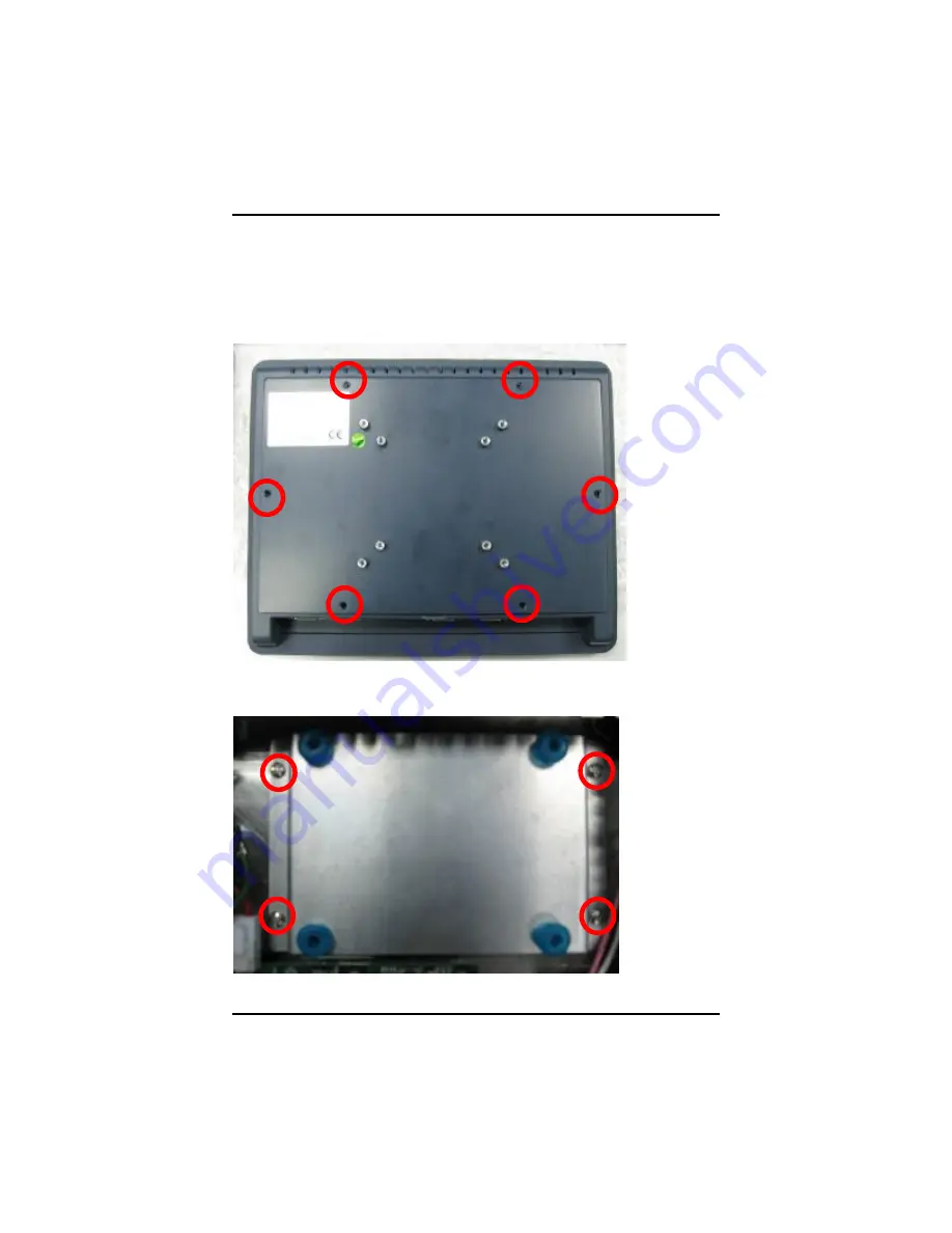
2.5  HDD Installation 

The GOT-5120TL provides a convenient drive bay module for 
users to install 2.5

 IDE HDD. Please follow the steps: 

1.  Unscrew screws to remove the rear chassis. 


2.  Unscrew 4 screws from the HDD drive bracket, and take out 

HDD bracket kit to install 2.5

 HDD. 


Содержание GOT-5120TL

Страница 1: ...GOT 5120TL All in One 12 1 SVGA TFT Super Slim Fanless Touch Computer User s Manual...

Страница 2: ...usefulness of any information in this document AXIOMTEK does not make any commitment to update the information in this manual AXIOMTEK reserves the right to change or revise this document and or produ...

Страница 3: ...ons However there is no guarantee that interference will not occur in a particular installation If this equipment does cause harmful interference to radio or television reception which can be determin...

Страница 4: ...depending on the application environment 5 Turn OFF the system power before cleaning Clean the system using a cloth only Do not spray any liquid cleaner directly onto the screen The GOT 5120TL may co...

Страница 5: ...ents AXIOMTEK is a trademark of AXIOMTEK Co Ltd IBM PC AT PS 2 VGA are trademarks of International Business Machines Corporation Intel and Pentium are registered trademarks of Intel Corporation MS DOS...

Страница 6: ...net 12 2 4 Mountings Panel Wall Desktop VESA 13 2 4 1 Panel Mounting 13 2 4 2 Wall Mounting 14 2 4 3 Desktop Mounting 15 2 4 4 VESA ARM Mounting 17 2 5 HDD Installation 19 2 6 Wireless Card Installati...

Страница 7: ...46 3 15 Exit Without Saving 47 CHAPTER 4 DRIVERS INSTALLATION 48 4 1 System 48 4 2 Touch Screen 49 4 2 1 Specification GOT 5120TL 49 4 2 2 Driver Installation Windows XP 49 4 3 Embedded O S 52 4 3 1 W...

Страница 8: ...viii MEMO...

Страница 9: ...equipped with an 12 1 TFT LCD display and low power consumption AMD LX800 processor with FSB 500MHz The GOT 5120TL supports Windows XP Windows CE NET and Windows XP embedded The panel is able to inst...

Страница 10: ...ferent industrial harsh environments l A fuse helps prevent over voltage for power input l The front bezel meets the IP65 NEMA4 standard l For connecting other devices the GOT 5120TL also features sev...

Страница 11: ...Storage n One slot for CF card l Box header n One PATA 100 IDE 1 2 3 System Specification l 12 1 TFT LCD l Heat Dispensing Design l Disk drive housing n one 2 5 PATA drive option l Net Weight n 2 kg...

Страница 12: ...GOT 5120TL User s Manual Introduction 4 NOTE All specifications and images are subject to change without notice...

Страница 13: ...GOT 5120TL User s Manual Introduction 5 1 3 Dimensions This diagram shows you dimensions and outlines of the GOT 5120TL...

Страница 14: ...6 1 4 I O Outlets Please refer to the following illustration for I O locations of the GOT 5120TL No Function 1 POWER SWITCH AT 2 24VDC POWER 3 VGA 4 COM 2 RS 232 5 COM 1 RS 232 422 485 6 1 X ETHERNET...

Страница 15: ...tain the following items l GOT 5120TL x 1 l Panel Mount Kit x 6 l Driver CD x1 l Wall Mount Kit x1 l Wireless LAN kit optional l 2 5 HDD kit optional l Desktop Stand Kit optional l VESA ARM optional I...

Страница 16: ...t demand for example CF card The chapter will show you how to install the hardware It includes n CompactFlash Card n Serial Port n Ethernet n Mounting Way 2 1 CF card Installation The GOT 5120TL provi...

Страница 17: ...GOT 5120TL User s Manual Hardware Installation 9 Step 2 Find out the cover on the side of the system Step 3 Locate the CompactFlash TM socket and insert the card into the socket...

Страница 18: ...or Pin Signal Pin Signal 1 Data Carrier Detect DCD 6 Data Set Ready DSR 2 Receive Data RXD 7 Request To Send RTS 3 Transmit Data TXD 8 Clear To Send CTS 4 Data Terminal Ready DTR 9 Ring Indicator RI 5...

Страница 19: ...S 422 or RS 485 the pin assignments are listed below Signal Name Pin RS 422 RS 485 1 TX DATA 2 TX DATA 3 RX No connector 4 RX No connector 5 No connector No connector 6 No connector No connector 7 No...

Страница 20: ...ant with IEEE 802 3 standard and can be connected with a RJ 45 LAN connector Please refer to detailed pin assignment list below Pin Signal 1 TX Data transmission positive 2 TX Data transmission negati...

Страница 21: ...VESA There are several mounting ways for the GOT 5120TL Panel Wall Desktop and VESA mountings 2 4 1 Panel Mounting The GOT 5120TL is designed for panel mount application A set of standard mounting ki...

Страница 22: ...User s Manual Hardware Installation 14 2 4 2 Wall Mounting The GOT 5120TL is designed for Wall mounting application Please refer to the following steps Find out the screws as marked on the back side...

Страница 23: ...Manual Hardware Installation 15 2 4 3 Desktop Mounting The GOT 5120TL is designed for desktop mounting application Please refer to the following steps Step 1 Find out the screws as marked on the back...

Страница 24: ...GOT 5120TL User s Manual Hardware Installation 16 Step 2 Assemble the desktop stand to the chassis and fix the screws...

Страница 25: ...er s Manual Hardware Installation 17 2 4 4 VESA ARM Mounting Step 1 Find out the mounting holes as marked on the back side of chassis Step 2 Assemble the VESA ARM to the back side of the chassis and f...

Страница 26: ...GOT 5120TL User s Manual Hardware Installation 18 Step 3 VESA mounting Installation completed...

Страница 27: ...stallation The GOT 5120TL provides a convenient drive bay module for users to install 2 5 IDE HDD Please follow the steps 1 Unscrew screws to remove the rear chassis 2 Unscrew 4 screws from the HDD dr...

Страница 28: ...GOT 5120TL User s Manual Hardware Installation 20 3 Connect HDD cable Installation complete...

Страница 29: ...Card Installation The GOT 5120TL provides one miniPCI slot for user to install one wireless card When installing the wireless card refer to the following instructions and illustration 1 Open the back...

Страница 30: ...GOT 5120TL User s Manual Hardware Installation 22 3 There are two connectors on wireless LAN card One is MAIN and the other is AUX Connect antenna cable to MAIN connector on wireless LAN card...

Страница 31: ...GOT 5120TL User s Manual Hardware Installation 23 MEMO...

Страница 32: ...ly or press the Del and or Ctrl Alt and Esc keys simultaneously when the following message appears at the bottom of the screen during POST Power on Self Test TO ENTER SETUP PRESS DEL KEY If the messag...

Страница 33: ...e color from total 16 colors F2 to select color forward Shift F2 to select color backward F3 key Reserved F4 key Reserved F5 key Restore the previous CMOS value from CMOS only for Option Page Setup Me...

Страница 34: ...the Setup Page you intend to configure then press Enter to accept or enter its sub menu NOTE If your computer can not boot after making and saving system changes with Setup the Award BIOS will reset y...

Страница 35: ...lue you want in each item l Date The date format is day date month year Press F3 to show the calendar day It is determined by the BIOS and read only from Sunday to Saturday date It can be keyed with t...

Страница 36: ...items Directly key in the information and press Enter This information should be provided in the documentation from your hard disk vendor or the system manufacturer If the HDD interface controller su...

Страница 37: ...29 All But Diskette The system booting will not stop for a disk error it will stop for other errors All But Disk Key The system booting will not stop for a keyboard or disk error it will stop for oth...

Страница 38: ...t you select the 1 st 2 nd and 3 rd devices that the system will search for during its boot up sequence The wide range of selection includes USB CDROM HDD 0 HDD 1 and so on l Boot Other Device This it...

Страница 39: ...second by the keyboard The function is always 6 characters per second l Typematic Delay Msec This option defines how many milliseconds must elapse before a held down key begins generating repeat chara...

Страница 40: ...User s Manual Phoenix Award BIOS Utility 32 l Small Logo EPA Show If enabled the EPA logo will appear during system booting up if disabled the EPA logo will not appear Press Esc to return to the Main...

Страница 41: ...y with these options Auto 333MHz 400MHz 433MHz and 500MHz The default setting is Auto l Memory Frequency This item helps you set main memory frequency When using an external graphics card it can be ad...

Страница 42: ...uration options are CRT Flat Panel and Panel CRT The default value is Panel CRT l Flat Panel Configuration The configuration is for resolution of flat panel which locks to 800 600 Press Esc twice to r...

Страница 43: ...item and press Enter to view the sub menu Super IO Device Onboard Serial Port 1 2 3 Select an address and corresponding interrupt for the serial port Options 3F8 IRQ4 2F8 IRQ3 3E8 IRQ10 2E8 IRQ11 338...

Страница 44: ...E Primary Secondary Master Slave UDMA Select the mode of operation for the IDE drive Ultra DMA 33 66 100 133 implementation is possible only if your IDE hard drive supports it and the operating enviro...

Страница 45: ...and press Enter to view the sub menu Onboard Device Onboard Audio Use this item to enable or disable the onboard Audio function Onboard USB1 1 Enable this item if you are using the EHCI USB1 1 contro...

Страница 46: ...GOT 5120TL User s Manual Phoenix Award BIOS Utility 38 l ITE8888 Configure Scroll to this item and press Enter to view the sub menu ITE8888 Configure Press Esc twice to return to the Main Menu page...

Страница 47: ...l ACPI Function This item allows you to enable disable the Advanced Configuration and Power Management ACPI The function is always Enabled l Power Management This option allows you to select the type...

Страница 48: ...owered down while other devices remain active l Modem Use IRQ If you want an incoming call on a modem to automatically resume the system from a powersaving mode use this item to specify the interrupt...

Страница 49: ...ould change default settings l PNP OS Installed Select Yes if the system operating environment is Plug and Play aware e g Windows 95 The default value is No l Init Display First This item allows you t...

Страница 50: ...mpliant with the Plug and Play standard whether designed for PCI or ISA bus architecture The default value is PCI ISA PnP l DMA Resources When resources are controlled manually assign each system DMA...

Страница 51: ...parameters for critical voltages temperatures and fan speed of the board l Current SYSTEM Temp Show you the current system temperature l Current CPU Temp The current system CPU temperature will be aut...

Страница 52: ...12 Load Optimized Defaults This option allows you to load your system configuration with default values These default settings are optimized to enable high performance features To load CMOS SRAM with...

Страница 53: ...may also press Esc to abort this selection and not enter a password To disable the password just press Enter when you are prompted to enter a password A message will confirm the password is getting d...

Страница 54: ...BIOS Utility 46 3 14 Save Exit Setup This section allows you to determine whether or not to accept your modifications Type Y to quit the setup utility and save all changes into the CMOS memory Type N...

Страница 55: ...ility 47 3 15 Exit Without Saving Select this option to exit the Setup utility without saving changes you have made in this session Type Y and it will quit the Setup utility without saving your modifi...

Страница 56: ...ON 4 1 System GOT 5120TL supports Windows 2000 XP To facilitate the installation of system driver please carefully read the instructions in this chapter before start installing 1 Insert Driver CD and...

Страница 57: ...onverter inside Power Input 2 7V 5 5V Power Consumption Active 3 6mA Idle Mode 1 0mA 4 2 2 Driver Installation Windows XP The GOT 5120TL provides a touch screen driver that users can install it under...

Страница 58: ...GOT 5120TL User s Manual Installation of Drivers 50 3 Click Start menu and select PenMount Utilities and then a PenMount Control Panel pops out Note Please choose COM3 for touch screen installation...

Страница 59: ...tion of Drivers 51 4 Select the Standard Calibrate tab 5 Calibration To adjust the display with touch panel click Calibration and follow the calibrate point to do calibration there are five points on...

Страница 60: ...Resolution 800x600 n 10 100 base T Ethernet n Compact Flash n Onboard Audio n Touch Screen PenMount Touch screen GOT 5120TL has Penmount touch screen on COM3 which is disabled by default Before you ca...

Страница 61: ...DD n USB n PS2 Keyboard and mouse n CRT LCD display n 10 100 base T Ethernet n Compact Flash n Onboard Audio n Audio n Touch Screen Calibration Touch screen In this image we add PenMount Touch drivers...

Страница 62: ...ion points on two COM4 After installing XP it sometimes appears two COM4 or one COM4 and one COM5 with exclamation points To remove them please follow the steps below In device manager it appears two...

Страница 63: ...e two COM4 or one COM4 and one COM5 with exclamation points in device manager 2 Choose first COM4 and enter properties resources Set Configuration Manually Untick the Use automatic settings 1 Setting...

Страница 64: ...Manual Appendix 56 1 Enter properties port setting Advanced 2 COM Port Number COM1 in use 3 Press OK to leave Choose second COM4 or COM5 properties resources Set Configuration Manually Untick the Use...

Страница 65: ...000 2 IRQ 03 COM2 3 I O Range 02F8 02FF COM1 1 Enter properties port setting Advanced 2 COM Port Number COM2 in use 3 Press OK to back to Device Manager and restart Windows After restarting windows tw...

Страница 66: ...removing exclamation point on Secondary IDE Channel Double click the file Lx800ide reg where is under the folder of GOT 5120TL 621 Driver After you install this Lx800ide reg to the registry the excla...

Отзывы: