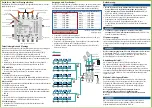
Connectors, switches, mounting brackets:
The single-cable multi-switch has the connections, switches and mounting
brackets shown.
4 Inputs for Universal Quattro LNB
Rotary switch
Quattro / Wideband
2 Inputs for Wideband LNB 1
2 Inputs for Wideband LNB 2
DC connector
Terrestrial input
Subscriber output 1
equipotential bonding
connector
Subscriber outputs 2
Trunk outputs for cascading
Mounting bracket
Mounting bracket
Mounting bracket
Mounting bracket
Equipotential bonding and mounting:
The device and the outer conductors of the coaxial cables must be connected
to the equipotential bonding. This serves to avoid dangerous overvoltages
(caution: fire/life hazard) according to EN 60728-11.
Use the equipotential bonding connection at the device.
Use, for example, a QEW earthing angle with SAK patch cables at the inputs
and CFA 7-01 earth connection blocks at the subscriber outputs of the
device.
Mount the device on a flat surface. Use appropriate mounting screws and
the mounting brackets of the device.
RF installation:
Use highly shielded coaxial cables with F connectors. Suitable cables and
connectors can be found in the current AXING at www.axing.com.
Quattro LNB:
Set the rotary switch to
Quattro
.
Connect the SAT inputs
LV
,
LH
,
HV
and
HH
of the multiswitch to the LNB of
your SAT reception antenna.
Wideband LNB:
The single-cable multiswitches can be used with wideband LNB with an
oscillator frequency of 10.4 GHz.
Set the rotary switch to
WB
.
Connect the first wideband LNB to the left connectors
V
and
H
.
Connect the second wideband LNB to the right connectors
V
and
H
.
Terrestrial:
Feed the output signals of a terrestrial amplifier or a CATV amplifier into the
terrestrial input.
Subscriber outputs
Connect the subscriber outputs of the multiswitch to the antenna wall
outlets.
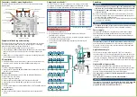
Outputs and user bands*:
The SES 5216 has two subscriber outputs. At each of these, 16 user bands
are available. An alternative user band assignment for CATV networks up to
1218 MHz is also possible (this must be ordered at the purchase).
For receivers according to EN 50607, all 16 user bands can be used.
UB 1
975 MHz
UB 9
1375 MHz
UB 2
1025 MHz
UB 10
1425 MHz
UB 3
1075 MHz
UB 11
1475 MHz
UB 4
1125 MHz
UB 12
1525 MHz
UB 5
1175 MHz
UB 13
1575 MHz
UB 6
1225 MHz
UB 14
1625 MHz
UB 7
1275 MHz
UB 15
1675 MHz
UB 8
1325 MHz
UB 16
1725 MHz
Eight user bands can be used for
EN 50494 receivers.
* Customised user band configuration
possible.
Assign each user band only once.
Use programmable single-cable antenna wall outlets SSD 6-xx for
interference-proof operation.
For multi-tuner devices (Twin or Quatto), assign the appropriate number of
user bands to the antenna wall outlet.
Connect the user band with the highest frequency (UB 16) using the
shortest cable.
2 x SCO 2-10
Wideband-LNB
DVB-C
CFA 7-01
UB8
SAT TV
EN 50607
UB7
SAT TV
EN 50607
UB6
SAT TV
EN 50607
UB5
SAT TV
EN 50607
UB4
SAT TV
EN 50607
UB3
SAT TV
EN 50607
UB2
SAT TV
EN 50607
UB1
SAT TV
EN 50607
UB8
SAT TV
EN 50494
UB7
SAT TV
EN 50494
UB6
SAT TV
EN 50494
UB5
SAT TV
EN 50494
UB4
SAT TV
EN 50494
UB3
SAT TV
EN 50494
UB2
SAT TV
EN 50494
UB1
SAT TV
EN 50494
UB12
SAT TV
EN 50607
UB11
SAT TV
EN 50607
UB10
SAT TV
EN 50607
UB9
SAT TV
EN 50607
UB16
SAT TV
EN 50607
UB15
SAT TV
EN 50607
UB14
SAT TV
EN 50607
UB13
SAT TV
EN 50607
SES 5216-06
CFA 11-00
QEW 5-06
SZU 99-06
5 × SAK 21-02
Coax
Equipotential bonding
Cascading:
If you do not connect any further single cable multiswitches, then
terminate the cascade outputs at the bottom of the device with
DC-decoupled 75 Ohm terminating resistors.
(e. g. CFA 11-00 not
included in delivery).
Up to three single cable multiswitches can be connected to one cascade.
Connect the outputs of the single cable multiswitch with the inputs of
the next single cable multiswitch units.
Use F/F Quickfix adapters CFA 4-01 or highly shielded coaxial cables with
F-connectors (not included).
Terminate the outputs of the last device with DC-isolated 75 Ohm
terminating resistors
(e. g. CFA 11-00 not included in delivery)
.
Power supply:
The single-cable multiswitch is supplied via an external power supply
unit SZU 99-06 (not included in the delivery). This power supply unit
also supplies the connected LNBs and any cascade modules that may be
connected.
The total supply current via the DC connection must not exceed 1 A.
Check that the current consumption of all connected components does
not exceed 1 A. If necessary, connect another external power supply unit
SZU 99-06 to a cascade unit.
Application example:
16 TV devices with tuners which support
EN 50607
are connected to
subscriber output 1. 8 TV devices with tuners which support
EN 50464
are
connected to subscriber output 2 (for further application examples, please
refer to www.axing.com). If different receivers (EN 50607/EN 50464) are
connected to one subscriber output, ensure that the user bands are assigned
correctly.
Single cable or legacy mode:
The single-cable multi-switch automatically detects which mode the
connected receiver requires and provides the appropriate signal (in single-
cable mode the user bands, in legacy mode the polarisation level). The
detection is performed separately for each subscriber output.
The legacy mode cannot be used with programmable antenna wall
outlets SSD 6-xx!
The legacy mode cannot be used with wideband LNBs!
To prevent a receiver which is not suitable for single-cable operation
switching the subscriber output to legacy mode, we recommend
programmable SSD 6-xx antenna wall outlets.


