2017-10-03 | Technical improvements, changes in design, printing- and other errors expected.
15
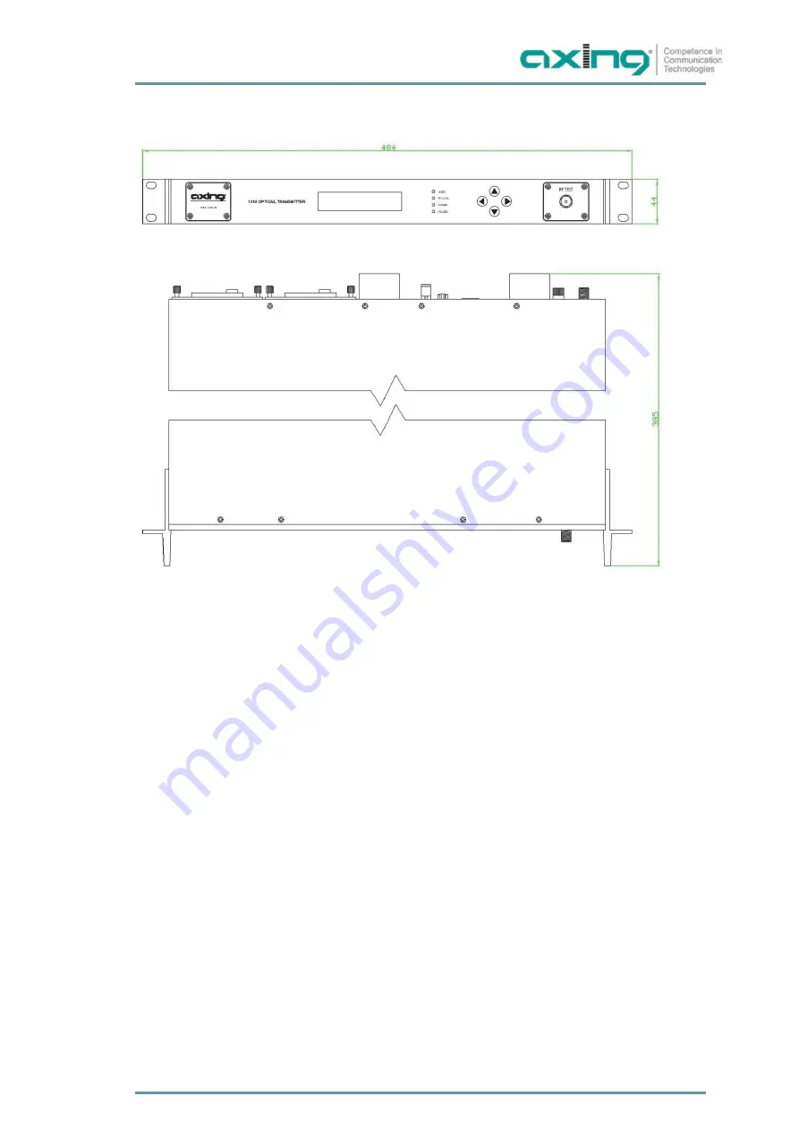
6.4.
Outlines Drawing
Dimensions are in mm.
Страница 1: ...OTX 1310 10 Optical Transmitter Operation Instructions...
Страница 2: ...ront and rear panel 5 2 1 Operating elements on the front panel 5 2 2 Connectors on the rear panel 6 3 Installation 7 3 1 Menu Interface 8 4 WEB Management 10 4 1 Parameters 10 4 2 Settings 11 4 3 Inf...
Страница 3: ...ill overload and damage the laser The optical transmitter should be stored in a ESD protection environment such as a ESD protection container and cannot be stored with corrosive cargo The store temper...
Страница 4: ...tter has following functions AGC MGC mode Low noise DFB laser Adjustable OMI SNMP Simple Network Management Protocol for administration and monitoring Furthermore it has two redundant plug in power su...
Страница 5: ...ser Temperature T COOL CURRENT mA Power supply 24 4V 5 4V 5 4V s Voltage detecting IP address Gateway OMI Inner temperature 2 LEDs green means that it works fine red meansfailed RF is for input levels...
Страница 6: ...Technical improvements changes in design printing and other errors expected 2 2 Connectors on the rear panel 6 6 1 2 3 4 5 7 8 1 RF Input Port 2 Grounding 3 RJ45 Web Management Interface 4 RS 232 5 Ou...
Страница 7: ...65VAC Connect the optical fibre with the optical output Make sure the connection is cleanded before use Connect the electric power and turn on the power switch The power supply LEDs are displaying the...
Страница 8: ...her errors expected RF Menu Press RF Gain Mode RF Gain Mode OMI Level OMI Level Normal OMI Adjust RF Attenuation OMI Adjust RF Attenuation OMI Adjust RF Attenuation OMI Adjust RF Attenuation OMI Adjus...
Страница 9: ...Current 53mA Laser Temp 25 3 Laser Cool Current 100mA Optical Wave Length 1310 00nm System Menu Firmware Version V1 0 Series Number System Temp 32 Power1 24 4V 24 4V Power1 5 4V 5 4V Power1 5 4V 5 4V...
Страница 10: ...ment Enter 192 168 1 1 into your web browser to get the following web interface The default password is admin After the login 5 items are displayed on the web interface Parameters Settings Information...
Страница 11: ...ich are displayed here can be changed AGC and MGC mode can be selected RF Attenuation from 0 12dB can be set when MGC mode is activated OMI can be set from 5 5dB 4 3 Information Here general informati...
Страница 12: ...10 03 Technical improvements changes in design printing and other errors expected 4 4 Network configuration Here the following parameters according to customer network can be set 4 5 Change password...
Страница 13: ...h the display output laser power is not correct Ring flange or test jumper connection is dirty Change the output laser power sensor Clean the connection Change the test jumper Test jumper connection m...
Страница 14: ...SM Optical Connector SC APC 6 2 RF characteristics Parameter Unit Value Frequency Range MHz 47 1002 RF Input Return Loss dBm 16 RF Input Level dB V 75 85 Flatness dB 0 75 CNR1 dB 50 CSO1 dBC 60 CTB1 d...
Страница 15: ...2017 10 03 Technical improvements changes in design printing and other errors expected 15 6 4 Outlines Drawing Dimensions are in mm...
Страница 16: ...Operation Instructions OTX 1310 10 Optical Transmitter 16 2015 12 04 AXING AG Swizzerland Technical data are subject to change errors and omissions excepted...