


MPR-3014WF-xM
- 8 -
Doc# 041314
AWID PROPRIETARY
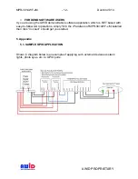
2.2.1. General Purpose Input/Output
Terminal block MPR-3014WF-xM 4 inputs & 4 outputs (optically isolated)
Pin
# Function
description Pin
# Function
description
1 Output
1
6 Input
Common
2 Output
2
7 Input
4
3 Output
3
8 Input
3
4 Output
4
9 Input
2
5
Output
Common 10 Input
1
The four general-purpose inputs that use photo diodes are used to accept TTL input
commands. Each input requires 15 mA and 5V to activate. The four outputs are solid
state relays, with 0.03 uA off-state leakage current and the ability to sink 120 mA at a
breakdown voltage of 400V DC. All four outputs are protected with reverse clamping
diodes, and ready to drive inductive loads. The floating arrangement eliminates any
ground loop considerations.
2.2.2. RS-232
Pin#
Function
description
Pin
# Function
description
1 DCD 5 GND
2 RXD 6 DSR
3 TXD 7 RTS
4 DTR 8 CTS
2.3. MEASURING READ DISTANCE
Make sure you know the tag types. For instance, EPC tags must be pre-programmed to
be read. In certain readers and tags, the user must also be mindful of the tag s
orientation and the reader s antenna orientation, what mounting surface the tags are
designed for and how the tags are supposed to be mounted. Any departure from its
intended purpose will drastically affect the reader s ability to energize the tag and its
read range.
When measuring the reader s read range, make sure that the tag is properly oriented to
the reader antenna, and for optimum performance, be sure the operator s finger is not
within three (3) inches of the tag s antenna surface.
3. INSTALLATION PROCEDURE
This section provides installation and operation information for MPR-3014WF-xM readers.
3.1. PARTS LIST