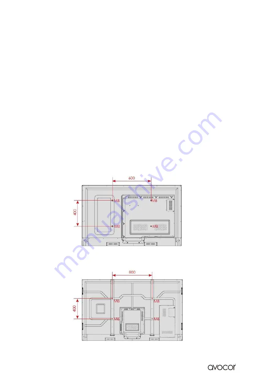
AVOCOR AVE-6520 Скачать руководство пользователя страница 4

v.05_12_2018 


AVE-6520


AVE-7520 / AVE-8620


Installation Guide 

When installing the displays please follow the installation manual from the manufacturer 
for the type of mount you have selected.  

Make sure you use the upper and lower handles on the back of the display while lifting or 
moving the display, to avoid touching the front panel during the move. 

When unpacking, and carrying the display please follow these guidelines: 


2 people are needed for displays up to 65”


3 people are needed for displays up to 75” & 86”


Before installing, please make sure the wall is strong enough to hold the necessary weight 
of the display and the mount. 

Step 1. 

Keep the display facing the ground and place it on a flat object. 

Step 2.

 Remove the 4 screws (M8*15) from the back of the display. 

Step 3

. Align the mounting arms with the mounting holes and attach the brackets to 

the display using the screws removed in Step 2. 

Caution:

 Use max 15mm long screws, 8mm Metric - Longer screws will damage the display 


Содержание AVE-6520

Страница 1: ...Quick Start Guide Models AVE 6520 AVE 7520 AVE 8620...

Страница 2: ...es 5 The Remote Control 6 Switching the display on and off 7 Source Selection 8 Connecting to the Display a Connecting to an external PC using an HDMI connection b Connecting to an external PC using a...

Страница 3: ...ing 1 Avocor Interactive LED Display 2 Accessory Carton Quick Start Guide Remote Control Batteries USB Drive 2x Touch Stylus 1x 3mm 1x 6mm 1x Eraser 1x 2m US Power Cable 2x 3m HDMI Cable 1x USB A USB...

Страница 4: ...lay please follow these guidelines 2 people are needed for displays up to 65 3 people are needed for displays up to 75 86 Before installing please make sure the wall is strong enough to hold the neces...

Страница 5: ...v 05_12_2018 5 The Display at a Glance Front View Rear View...

Страница 6: ...v 05_12_2018 6 Speakers Power Button Front Buttons Power Switch Power Supply Plug OPS Slot Rear Parts...

Страница 7: ...turn on the OPS or go back to the previous source Volume Up Down Press these two buttons to decrease or increase the volume Freeze Press the button to freeze the display Press again to release it Bla...

Страница 8: ...v 05_12_2018 8 AVE 6520 7520 8620 Display Inputs Side Ports Rear Ports...

Страница 9: ...o restore Turns off the sound Increases or decreases the volume by pressing the and keys Selects light settings Navigates through submenus and settings Selects highlighted menu choice MENU Opens the o...

Страница 10: ...or the like Don t recharge heat disassemble short or throw batteries into a fire Notes on Remote Control Operation Make sure that there is nothing obstructing the infrared beam between the remote con...

Страница 11: ...The power LED indicator lights Red to indicate that the display is in standby mode 4 Press the Power button and the power LED indicator on the left hand side of the display will then light up in green...

Страница 12: ...ctive signal from the chosen source the screen will display the following message No Signal Connecting the Display Proceed as follows to connect the display to your video sources external controller W...

Страница 13: ...on the external PC 3 Using the Remote Control select the HDMI source button or press the Source Button see operating buttons on the Front Connection bar to select HDMI This display supports the VESA...

Страница 14: ...B port USB B of the touchscreen and to the USB port USB A on the external PC 3 Connect an audio cable to the audio output of the external PC and to the audio output of the screen 4 Using the Remote Co...

Страница 15: ...al PC 2 Connect the enclosed USB cable to the touch USB port USB B of the touchscreen and to the USB port USB A on the external PC 3 Using the Remote Control select the DisplayPort source button or pr...

Страница 16: ...input on the display Connecting the Display to a Host Computer 1 Connect the signal cable to the display and then turn on the display 2 Connect the USB Cable USB Type B connector to the display 3 Con...

Страница 17: ...ible Step 4 Secure the OPS module in position by screwing it onto the display input panel using the screws that were removed earlier Step 5 Ensure the installation is complete before turning on the po...

Страница 18: ...w to resolve them on the avocor Website www avocor com support Organisation Name Contact Person 1st Contact Number Landline 2nd Contact Number Mobile Cell Email Address of on site repair or unit excha...

Страница 19: ...v 05_12_2018 19 Notes...

Страница 20: ...v 05_12_2018 20...

Отзывы: