background image

 Chapter 3: Operations        

39

4.

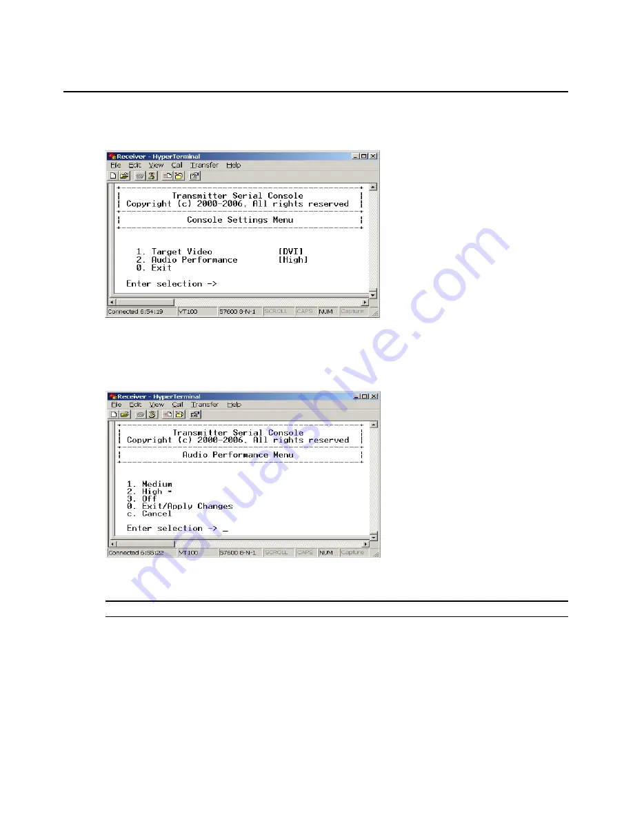
Choose 

Console Settings

. The Console Settings Menu will appear. The current audio 

performance setting is displayed beside menu item 2. Audio Performance.

Figure 3.28: Transmitter Console Settings Menu

5.

Choose 

Audio Performance

. The Audio Performance Menu will appear.This menu shows you 

the audio settings that you can choose from. The current setting is indicated by an 


asterisk symbol 

*

Figure 3.29: Transmitter Audio Performance Menu

6.

Type the number that corresponds to the audio setting you wish to apply and press 

Enter

.

NOTE: 

If you choose “off,” audio support will be disabled.

7.

To confirm your selection and exit the screen, type


0


(zero) and press 

Enter

. The unit resets 

after you press 

Enter

.

Содержание Emerge ECMS2000U

Страница 1: ...EmergeTM ECMS2000U Digital Workstation Extender Installer User Guide ...

Страница 2: ...pment in a residential area is likely to cause harmful interference in which case the user will be required to correct the interference at his own expense Canadian Notification This digital apparatus does not exceed the Class A limits for radio noise emissions from digital apparatus set out in the Radio Interference Regulations of the Canadian Department of Communications Le présent appareil numér...

Страница 3: ...station Extender Installer User Guide Avocent the Avocent logo and Emerge are registered trademarks of Avocent Corporation All other marks are the property of their respective owners 2006 Avocent Corporation All rights reserved 590 704 501A ...

Страница 4: ...ulated dangerous voltage within the product s enclosure that may be of sufficient magnitude to constitute a risk of electric shock to persons Power On This symbol indicates the principal on off switch is in the on position Power Off This symbol indicates the principal on off switch is in the off position Protective Grounding Terminal This symbol indicates a terminal which must be connected to eart...

Страница 5: ......

Страница 6: ...allation 10 Chapter 3 Operations 13 Overview 13 LED Identification 13 Accessing the System 14 The Serial Menu 14 Accessing the serial menu 14 Navigating the serial menu 16 Configuring Network Settings 16 Detecting a Transmitter IP Address 23 Authentication 24 Flash Upgrading your Emerge Digital Workstation Extender 28 Restoring Factory Default Settings 33 Resetting the Avocent Emerge ECMS2000U Ext...

Страница 7: ...v Avocent Emerge ECMS2000U Extender Installer User Guide Appendix A Technical Specifications 41 Appendix B Factory Default Settings 46 Appendix C Technical Support 47 Appendix D Troubleshooting 48 ...

Страница 8: ...k Configuration Menu 21 Figure 3 11 Receiver Network Configuration Menu 22 Figure 3 12 Receiver Main Menu 23 Figure 3 13 Network Configuration Menu 23 Figure 3 14 Transmitter IP Configuration Menu on the Receiver 24 Figure 3 15 The Receiver Security Configuration Menu 25 Figure 3 16 Password Reset Mode 26 Figure 3 17 Transmitter Security Configuration Menu 27 Figure 3 18 Transmitter Firmware Manag...

Страница 9: ...of Figures vii Figure 3 28 Transmitter Console Settings Menu 39 Figure 3 29 Transmitter Audio Performance Menu 39 Figure 3 30 Receiver Console Settings Menu 40 Figure 3 31 Receiver Audio Performance Menu 40 ...

Страница 10: ...d Refresh Rates 7 Table 2 2 Default network settings 10 Table 3 1 RJ 45 Connector LEDs 13 Table A 1 User Access Node Product Specifications 41 Table A 2 Computer Access Node Product Specifications 44 Table B 1 Avocent Emerge ECMS2000U Extender 46 LIST OF TABLES ...

Страница 11: ...ix Avocent Emerge ECMS2000U Extender Installer User Guide ...

Страница 12: ...e computers securely housed in a corporate data center This desktop experience includes access for the desktop user to keyboard mouse video and audio devices The Avocent Emerge ECMS2000U Extender consists of The Computer Access Node that connects externally to the remote computer The User Access Node that is located at the user s desk Figure 1 1 Avocent Emerge ECMS2000U Extender Basic System CHAPT...

Страница 13: ...ished with the remote computer via the Computer Access Node No intervention is required from the user See Accessing the System on page 14 Ethernet addressing The User Access Node and the Computer Access Node are IP addressable devices this gives you the flexibility to locate back racked computers anywhere within your enterprise and at any distance from your desktop users The User Access Node and t...

Страница 14: ...llows you to perform administration and maintenance tasks for both the User Access Node and the Computer Access Node Examples of tasks you can perform include configuration of network settings and firmware Flash upgrades See The Serial Menu on page 14 Flash upgradeable Upgrade your firmware at any time using the XMODEM or HTTP protocols to ensure that your Avocent Emerge ECMS2000U Extender is alwa...

Страница 15: ... Extender delivers significantly lower TCO when compared to traditional distributed computer systems Centralized maintenance enables greater security and convenience as well as reduced workplace disruption and down time IT administration costs are also significantly reduced by housing all PCs in one central location Relocating the computer away from the user frees up valuable office space and redu...

Страница 16: ...ble not supplied Needed for non standard installations To connect a VGA monitor to the User Access Node A DVI to VGA adaptor not supplied To connect the Computer Access Node to a remote computer that has VGA video output A VGA to DVI I adaptor not supplied To connect the Computer Access Node to a remote computer that has DVI D video output A DVI D to DVI I adaptor not supplied To power the Compute...

Страница 17: ...can install the Avocent Emerge ECMS2000U Extender in one of two ways 1 Point to point 2 Networked Point to point installation The following instructions will enable you to install your Avocent Emerge ECMS2000U Extender in a point to point configuration In a point to point configuration no administrator setup of the Computer Access Node or the User Access Node is required This enables you to instal...

Страница 18: ...daptor You must configure the Computer Access Node video settings for VGA through the serial menu For more information see Configuring Video Input Settings on page 36 4 Connect the Computer Access Node s audio and microphone connectors to the appropriately labeled ports on the back of the computer NOTE For CD quality audio you must configure the Computer Access Node and the User Access Node using ...

Страница 19: ...rals cables to the appropriately labeled ports on the back of the User Access Node 2 Connect the UTP cable to the RJ 45 port on the back of the User Access Node 3 Power up the User Access Node A connection will be automatically established with the remote computer NOTE VGA monitors can be connected to the User Access Node by using a DVI I to VGA adaptor Video USB Mic Line out ...

Страница 20: ...the power supply provided by Avocent To connect power to the User Access Node 1 Plug the external power supply s 2 5mm connector into the DC power jack on the rear of the User Access Node 2 Connect the detachable IEC power cord to the power supply 3 Plug the IEC power cord into an appropriate wall outlet Microphone Speakers Serial Computer Access Node Remote PC User Access Node Local Peripherals a...

Страница 21: ...ase in end to end latencies which may not be acceptable for all applications Figure 2 4 Networked Installation The Avocent Emerge ECMS2000U Extender has been pre configured with factory default network settings If you install only one Avocent Emerge ECMS2000U Extender on a subnet you do not need to change these default network settings If you install multiple units on the same subnet you will need...

Страница 22: ...ically established with the remote computer 4 Use the serial menu to re configure the network settings for the Computer Access Node For more information on how to do this see Configuring Network Settings on page 16 NOTE If the User Access Node and Computer Access Node are to be located on different subnets configure their network settings before you connect to the network NOTE If there are already...

Страница 23: ...12 Avocent Emerge ECMS2000U Extender Installer User Guide ...

Страница 24: ...e the Avocent Emerge ECMS2000U Extender via the serial menu LED Identification Front panel There are two blue LEDs on the front panel of the User Access Node The PWR LED will light up when the User Access Node has been powered up The ACTIVE LED will blink slowly until the User Access Node establishes a connection with the Computer Access Node When a connection has been established between the User...

Страница 25: ...work settings for the User Access Node Configure network settings for the Computer Access Node Set or change passwords Upgrade your firmware for the User Access Node and Computer Access Node Reset to factory defaults Set a session time out value Change the audio performance settings Accessing the serial menu You can access the serial menu via the serial port on the back of the User Access Node All...

Страница 26: ...nu Networked computer with a serial port Null modem serial cable male DB9 or three wire serial cable HyperTerminal emulation software or equivalent To access the serial menu 1 Connect one end of the serial cable to the serial port on the back of the Receiver 2 Connect the other end of the serial cable to the serial port of your PC 3 Launch HyperTerminal 4 Configure the HyperTerminal session for 57...

Страница 27: ...l bring you to a sub menu or to a screen where you can make configuration changes To exit a menu or screen and to confirm any configuration changes you have made type 0 zero and press Enter To navigate back up through the menus continue to type 0 and press Enter at each screen Configuring Network Settings The Avocent Emerge ECMS2000U Extender is shipped with default network settings pre configured...

Страница 28: ... If the password option is enabled you will be prompted for a password See Authentication on page 24 3 Type the password and press Enter The Transmitter Main Menu will appear Figure 3 3 Transmitter Main Menu NOTE The Reset option in the Transmitter Main Menu applies only to network settings 4 Choose Network Configuration The Network Configuration Menu will appear Figure 3 4 Network Configuration M...

Страница 29: ...eway 11 Type a valid Transmitter Default Gateway Press Enter to return to the Transmitter Network Configuration Menu 12 Type 0 zero and press Enter to return to the Network Configuration Menu 13 If you made a mistake and do not wish to save the changes you made to the network settings type C and press Enter 14 To confirm your changes and apply those settings type 0 zero and press Enter 15 A system...

Страница 30: ...ns 19 17 Type the password and press Enter The Receiver Main Menu will appear Figure 3 6 Receiver Main Menu 18 Choose Network Configuration The Network Configuration Menu will appear Figure 3 7 Network Configuration Menu ...

Страница 31: ...made a mistake and do not wish to save the changes you made to the network settings type C and press Enter 23 To confirm your changes and apply those settings type 0 zero and press Enter 24 The Receiver will now automatically reset to apply the new network configuration You will be automatically returned to the Appliance Selection Menu screen The connection to the Transmitter will be automatically...

Страница 32: ...ns 21 3 Type the password and press Enter The Receiver Main Menu will appear Figure 3 9 Receiver Main Menu 4 Choose Network Configuration The Network Configuration Menu will appear Figure 3 10 Network Configuration Menu ...

Страница 33: ...nu 10 Choose Receiver Default Gateway 11 Type a valid Receiver Default Gateway Press Enter to return to the Receiver Network Configuration Menu 12 Type 0 zero and press Enter to return to the Network Configuration Menu 13 If you made a mistake and do not wish to save the changes you made to the network settings type C and press Enter 14 To confirm your changes and apply those settings type 0 zero ...

Страница 34: ...ich the Transmitter is attached NOTE If the Transmitter receives its power from an external power supply disconnect the Transmitter from that external power supply 1 Choose option 1 to access the Receiver menu If the password option is enabled you will be prompted for a password See Authentication on page 24 2 Type the password and press Enter The Receiver Main Menu will appear Figure 3 12 Receive...

Страница 35: ...ust enter the detected IP address manually by choosing Transmitter IP Address from the Transmitter IP Configuration Menu Authentication By default two passwords are required to access the Avocent Emerge ECMS2000U Extender via the serial menu One password is for access to the serial menus that control the Receiver The other password is for access to the serial menus that control the Transmitter In ...

Страница 36: ...Confirm the new password If successful you will see a message stating that the password has been changed 5 Press Enter 6 To save your changes and exit the menu type 0 zero and press Enter To change the Receiver password 1 Choose Change Console Password on the Security Configuration Menu You will be prompted to enter your current password 2 Type your current password and press Enter You will be pro...

Страница 37: ...cter hex code Read out the code exactly as it appears on the serial menu The Technical Support Specialist will now give you another 16 character hex sequence 6 In the serial menu at the Key prompt type the 16 character hex sequence provided to you by Avocent Technical Support Press Enter 7 The default password is now active For information on how to change your password see Authentication for the ...

Страница 38: ...rm the new password If successful you will see a message stating that the password has been changed 5 Press Enter 6 To save your changes and exit the menu type 0 zero and press Enter To change the Transmitter password 1 Choose Change Console Password on the Security Configuration Menu You will be prompted to enter your current password 2 Type your current password and press Enter You will be promp...

Страница 39: ...ce provided to you by Avocent Technical Support Press Enter 7 The default password is now active For details on how to change your password see Authentication for the Transmitter on page 26 Flash Upgrading your Emerge Digital Workstation Extender You can Flash upgrade your Receiver and Transmitter You can Flash upgrade your Avocent Emerge ECMS2000U Extender using either XMODEM or HTTP The Receiver...

Страница 40: ...o the Transmitter is lost You will be automatically returned to the Appliance Selection Menu screen NOTE If the Transmitter determines that the upgrade file is invalid the Transmitter cancels the upgrade and maintains the previous firmware version A message displays indicating that the upgrade has failed To Flash upgrade your Transmitter using HTTP 1 Download the Transmitter upgrade file from Avoc...

Страница 41: ...ting Firmware update successful Resetting Appliance During reset the Transmitter will drop the connection to the Receiver A second system message will appear that states Connection to the Transmitter is lost You will be automatically returned to the Appliance Selection Menu screen NOTE If the Transmitter determines that the upgrade file is invalid the Transmitter cancels the upgrade and maintains ...

Страница 42: ...n to the Receiver will be restored NOTE If the Receiver determines that the upgrade file is invalid the Receiver cancels the upgrade and maintains the previous firmware version A message will display indicating that the firmware upgrade has failed To Flash upgrade your Receiver using HTTP 1 Download the Receiver upgrade file from Avocent 2 Activate the serial menu as described in Accessing the ser...

Страница 43: ... example http 192 168 0 1 8080 RX dld NOTE If the server is set up on standard port 80 the port information can be omitted 8 To initiate the file transfer press Enter The connection to the Transmitter will be dropped 9 When the transfer has completed a message will display stating Firmware update successful Resetting Appliance 10 The connection to the Transmitter will be restored NOTE If the Recei...

Страница 44: ...Receiver will drop the connection to the Transmitter When reset is complete the Receiver will restore the connection to the Transmitter using the new settings To restore the Transmitter factory default settings 1 Activate the serial menu as described in Accessing the serial menu on page 14 2 Choose option 2 to access the Transmitter menu If the password option is enabled you will be prompted for a...

Страница 45: ...ansmitter Main Menu will appear 4 Choose Reset Appliance The Reset Appliance Menu will appear 5 Choose Transmitter Reset to initiate the reset A message will be displayed on the serial menu that states Resetting appliance During reset the Transmitter will drop the connection to the Receiver A second system message will appear that states Connection to the Transmitter is lost You will be automatica...

Страница 46: ...n boot and FPGA firmware version numbers and the manufacturing part number All values are read only Figure 3 24 Receiver Appliance Information Menu To view Transmitter system information 1 Activate the serial menu as described in Accessing the serial menu on page 14 2 Choose option 2 to access the Transmitter menu If the password option is enabled you will be prompted for a password See Authentica...

Страница 47: ... computer to your monitor To enable the system to transmit the appropriate video signal for your monitor you must first configure the video input settings for the Transmitter NOTE Video display problems may occur if video input settings are not configured correctly 1 Activate the serial menu as described in Accessing the serial menu on page 14 2 Choose option 2 to access the Transmitter menu If th...

Страница 48: ...n between the Receiver and the remote computer By default if the Receiver cannot immediately establish a connection with the remote computer it will retry once per second until a connection is successfully established You can change the default session retry settings using the serial menu To access the Session Retry Menu 1 Activate the serial menu as described in Accessing the serial menu on page ...

Страница 49: ...r to disable audio support There are three settings available high medium and off The high setting provides the best audio performance and should be used when high network bandwidth is available The medium setting should be used if network bandwidth is limited or if the network latency is high If you choose off audio support will be disabled NOTE To ensure that audio operates correctly configure t...

Страница 50: ...dio Performance Menu will appear This menu shows you the audio settings that you can choose from The current setting is indicated by an asterisk symbol Figure 3 29 Transmitter Audio Performance Menu 6 Type the number that corresponds to the audio setting you wish to apply and press Enter NOTE If you choose off audio support will be disabled 7 To confirm your selection and exit the screen type 0 ze...

Страница 51: ...Console Settings Menu will appear The current audio performance setting is displayed beside menu item 4 Audio Performance Figure 3 30 Receiver Console Settings Menu 5 Choose Audio Performance The Audio Performance Menu will appear This menu shows you the audio settings that you can choose from The current setting is indicated by an asterisk Figure 3 31 Receiver Audio Performance Menu 6 Type the nu...

Страница 52: ...o Port 16386 Keyboard Mouse Ports 4463 4464 4465 Control Extension Ports Number 1 Connectors RJ 45 User Ports Number PS 2 2 USB 4 DVI I video 1 audio microphone 1 audio line out 1 power jack 1 Type PS 2 USB Type A DVI I video Connectors 6 pin miniDIN PS 2 keyboard and mouse USB Type A USB keyboard and mouse DVI I female 3 5 mm stereo audio jacks line out and mic 2 5 mm DC power jack Encryption Typ...

Страница 53: ...ius 32 to 95 Farenheit Storage Temperature 20 to 60 Celsius 4 to 140 Farenheit Transit Temperature 30 to 60 Celsius 22 to 140 Farenheit Operating Humidity 10 to 90 noncondensing Storage Humidity 5 to 95 Supported Hardware Peripherals PS 2 keyboard and mouse USB keyboard and mouse speakers microphone Keyboard Standard 104 105 109 keyboards for PC Macintosh and Sun USB keyboards for PC Macintosh and...

Страница 54: ...lutions and refresh rates Video Standard DDC version 2B Color Depth 24 Bit Audio Standard PC99 Audio Performance High Performance Line out 44 1 kHz over stereo channels at a resolution of 16 bits Microphone 44 1 kHz over a single channel at a resolution of 16 bits Medium Performance Line out 8 kHz over stereo channels at a resolution of 16 bits Microphone 8 kHz over a single channel at a resolutio...

Страница 55: ...5 mm DC power jack Encryption Type Authenticated SSL Dimensions H x W x D 68 x 21 x 153 mm 2 68 x 0 83 x 6 02 in Weight 0 3 Kg 0 66 lb including cables Environmental Heat Dissipation 22 W H Power Consumption 6 W AC input power 100 240 V AC AC input current rating 1 A AC frequency 50 60 Hz DC input power 5 V DC input current rating 1 1 A Operating Temperature 0 to 35 Celsius 32 to 95 Farenheit Stor...

Страница 56: ...DDC version 2B Color Depth 24 Bit Audio Standard PC99 Audio Sampling 44 1 kHz over a single channel at a resolution of 16 bits Target Sync Types Analog input only Separate horizontal and vertical Safety and EMC Approvals and Markings UL FCC cUL CE Table A 2 Computer Access Node Product Specifications Continued ...

Страница 57: ... PRINT SCREEN OSD Inactivity Timer 00 hours 10 minutes OSD Inactivity Check Box Enabled Session Inactivity Timer 00 hours 10 minutes Session Inactivity Check Box Disabled Session Retry Timeout 1 second Audio Performance Medium Network Speed Auto Negotiate Password password Computer Access Node Name TX_ MAC address IP Address 192 168 13 2 Default Gateway 0 0 0 0 Netmask 255 255 255 0 Audio Performa...

Страница 58: ...or the fastest possible service To resolve an issue 1 Check the pertinent section of this manual to see if the issue can be resolved by following the procedures outlined 2 Check our web site at www avocent com support to search the knowledge base or use the on line service request 3 Call the Avocent Technical Support location nearest you Please have the product serial number available when contact...

Страница 59: ...de is draw ing sufficient power If the Computer Access Node cannot draw sufficient power from the remote computer you will need to obtain an external power supply unit for the Computer Access Node from Avocent If connected through a USB hub ensure that the hub can supply enough power Verify that the correct video setting has been configured in the Computer Access Node serial menu If the remote com...

Страница 60: ...e using Retest the mouse and keyboard by connecting them directly to the remote computer and reboo ting If one does not function correctly replace it No audio from speakers attached to User Access Node Ensure that the audio cable is securely plugged into the line out port of the remote computer should be color coded green Ensure that the speaker cable is securely plugged into the line out port of ...

Страница 61: ...onnectors on the remote computer Verify that the Computer Access Node is drawing sufficient power from the USB connections on the remote computer and that it has booted correctly If the green LED on the Computer Access Node is on the Computer Access Node is draw ing sufficient power If the Computer Access Node cannot draw sufficient power from the remote computer obtain an external power supply un...

Страница 62: ... Kouji machi Tsuruya Hachiman Blug 6F 2 4 Koujimachi Chiyoda ku Tokyo 102 0083 Japan TOKYO Tel 81 6 4806 7088 Fax 81 6 6300 0122 Nishi Nakajima Shin Osaka Blug 611 5 10 5 NIshi Nakajima Yodogawa ku Osaka 532 0011 Japan OSAKA E mail info ysol co jp URL http www ysol co jp 590 386 001A ...

Отзывы: