background image

Matrix Switching System

User Manual 

25 

7.0.3 LAN Web Configuration 

Open the 

Browser

, key in the default IP address: 

http://192.168.0.3

 to login the 

AV 

MATRIX Control

 configuration screen. Once the default IP address is be changed, 

please use the changed IP to login.   

The software controls signal connection between the corresponding input port and 

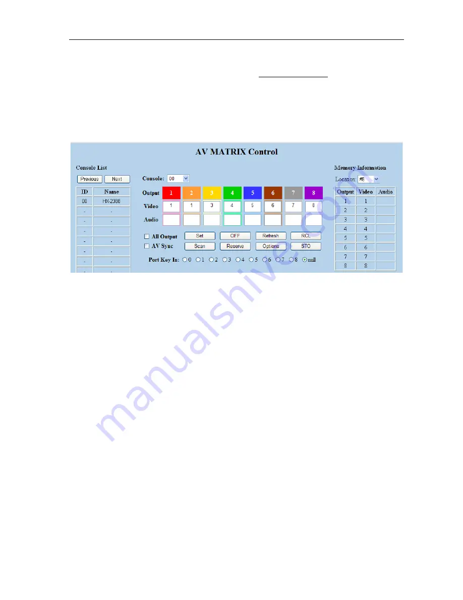
output port as required. The LAN main configuration screen is as below: 


Figure 7-8 LAN Web Configuration Screen 

)


HDMI is integrated Video/Audio switching equipment. Please only key in the Output 

Channel No. into the 

Video

 field, the 

Audio

 field value will be a default depends on the 

Video

 value automatically.   

)

 HX-2388 Device ID is fixed at 0. 

Scan:

 To search the device controlled by the LAN Web Configuration. When the 

Console List

 content is empty, you can click the 

Scan

 to research and update the 

Console List.   

Options:

 Allows you to configure the 

IP

 address. 

Set:

 Click this button to set the connected combinations both output and input ports. 

Refresh: 

To refresh the values of the configuration screen. Any changed settings directly 

on the HX-2388 equipment will not respond to the AV Matrix operating interface, you 

have to click the 

Refresh

 button to refresh the configuration screen so that showing the 

changed values. 

OFF: 

Disable the entire output channels.   

STO:

 The 

“Store Key”

 saves all current input/output corresponding relations. 

RCL:

 The 

“Retriever Key” 

retrieves the saved input/output corresponding relations. 

)

 For more relative information, please refer to 

5.0.1. Front Panel

.  

All Output:

 A Hot Key for you to set the same value to all


output channels. Select the 

All 

Содержание HX-2388

Страница 1: ...in any form or by any means without written permission from the product manufacturer Changes are periodically made to the information in this document They will be incorporated in subsequent editions...

Страница 2: ...o not use near water It is better to keep it in a dry environment The system should be installed indoor only Install either on a sturdy rack or desk in a well ventilated place Only using the power Ada...

Страница 3: ...ption 17 7 0 1 2 Software Activation 17 7 0 2 RS 232 Software Configuration 18 7 0 2 1 RS 232 Main Operation Interface 19 7 0 2 2 Disconnect Function Keys 21 7 0 2 3 Select all output DeSelect all out...

Страница 4: ...Matrix Switching System User Manual 3 HDMI EP DIP Switch Settings 37 Input Output Signal 39 Wiring Information Coding 39...

Страница 5: ...is unlike typical HDMI switchers only communication limited the distance through the HDMI EP devices you can over long distances to transmit signals HX 2388 Matrix Switcher is used mainly in TV broadc...

Страница 6: ...User Manual 5 1 0 2 Packing HDMI Matrix Device RS 232 Communication Connecting Cable Power Cord IR BOX LAN Line Controller 2 pcs of AAA battery HDMI Matrix Software CD User Manual 2 Rack Mount Bracke...

Страница 7: ...port and output port connection Supports computer video up to 1920 1200 Supports HDTV up to 1080p EDID management Copy from OUT port 1 3 0 Specifications Function HX 2388 Input Connector 8 x HDMI Typ...

Страница 8: ...put Channel Click the Output button then click the Input button to set the combinations Operation method No 2 STO or RCL Output Channel Click the STO or RCL button then click the Output button Operati...

Страница 9: ...gs will be saved in the memory permanently RCL The Retriever Key retrieves the saved input output corresponding relations Press the RCL key firstly Then make a random to select one of output channel k...

Страница 10: ...outlet of power source Power Switch To switch power ON or OFF the HDMI matrix device RS 232 Use the RS 232 connection cable to connect the computer serial port COM1 or COM2 to the RS232 communication...

Страница 11: ...er port modules up port is for DDC function down port is for VIDEO function For RJ 45 Connector daughter board modules equipment the connection has a collocation with HDMI EP please refer to the Appen...

Страница 12: ...trix Switching System User Manual 11 6 0 HDMI Matrix and Peripherals Connection Figure 6 1 HDMI Matrix System Connections Use the HDMI EP devices to extend the connection please refers to the Appendix...

Страница 13: ...anual 12 6 0 1 Input Output Connections Use the HDMI connecting cable to connect the Input Output serial port No 1 No 8 to the HDMI port of the DVD Player HDTV or HDMI EP Figure 6 2 Input Connections...

Страница 14: ...e computer can then be used to control the HDMI matrix after installation of application software Aside from using the front panel keys for switching operation you are also permitted to use the RS 232...

Страница 15: ...stem User Manual 14 The RS 232 Leg functions are described as below Pin No Leg Description 1 N u Null 2 TXD Send 3 RXD Receive 4 N u Null 5 GND Ground 6 N u Null 7 N u Null 8 N u Null 9 N u Null Figur...

Страница 16: ...Matrix Switching System User Manual 15 Figure 6 5 b The Matrix RS 232 port is defined as DCE...

Страница 17: ...r more convenient to react to the controller Please connect the IR BOX to the IR2 port that is on the rear panel Figure 6 6 IR Connection 6 0 4 Power connection Use the included power cord to connect...

Страница 18: ...ndow98 2000 7 NT XP Vista operating systems 32M internal memory or above 10M hard disk space or above CD ROM At least one serial communication port 7 0 1 2 Software Activation First you must power off...

Страница 19: ...port and output port as required The RS 232 main configuration screen is as below Figure 7 1 RS 232 Software Configuration Screen HX 2388 is HDMI switching equipment please select the Video check box...

Страница 20: ...t key This way you have selected Input 01 and Output 02 03 and 04 switching Step 3 First select the Output number key 01 to the right of the blue configuration area and select the Input number key 03...

Страница 21: ...onfigure the Port number and Baud rate Exit Click this button to exit the configuration screen Save Click this button to save the connected combinations both output ports and input ports Load Click th...

Страница 22: ...relations are shown in Figure 7 2 below Figure 7 2 First you have to disable the output ports including port 03 02 and 01 Step 1 First press down the output number keys 03 02 and 01 to the right of t...

Страница 23: ...ibed below Example Now you have an HX 2388 matrix with all input and output ports properly connected to the equipments The needed input output ports should be set to channel 1 input to all output port...

Страница 24: ...ple of the Store Function is described below Store all the present input output switching relations to Location 1 First select Location 1 as shown in the figure below Then click the Save key to save a...

Страница 25: ...s shown in Figure 7 6 a 7 0 2 7 Other Application Displays the presently saved switching status as shown in Figure 6 7 below Figure 7 7 When input corresponding to Output is enabling it shows the Outp...

Страница 26: ...evice controlled by the LAN Web Configuration When the Console List content is empty you can click the Scan to research and update the Console List Options Allows you to configure the IP address Set C...

Страница 27: ...ation is described as below Example Now there is an HX 2388 matrix having all the input output ports properly connected to the equipment If you want to set channel 1 input to channel 2 3 and 4 output...

Страница 28: ...tching relations to Location 2 First select Location 2 as shown in the figure below Then click the STO button to save the present input output switching relations to Location 2 Retrieve Function Descr...

Страница 29: ...re 7 11 Figure 7 13 In the Network Settings configuration you can set the IP information by yourself Fix IP or click the Enable DHCP check box to get the IP from the DHCP Float IP Click the Default bu...

Страница 30: ...Figure 7 14 The entire connected Device name will be showed on the Console List as Figure 7 15 For this model the software utility only shows an ID 00 for the Name HX 2388 presently When the Console L...

Страница 31: ...n to flicker 2 Press the NO 1 key of the Input channel Example 2 Switch the NO 1 and NO 2 input signals to each NO 1 and NO 2 output channels Key LCD Display Operation 1 Press the NO 1 key of the outp...

Страница 32: ...settings Key LCD Display Operation 1 Press the NO 2 key of the output channel then the input channels will begin to flicker 2 Press the NO 1 key of the Input channel 3 Press the ALL key on the front...

Страница 33: ...l 3 Press the STO key on the front panel The Store Memory begins to flicker about 8 seconds 4 Press the NO 1 key of the output channel to save the setting in the NO 1 channel 5 Press the ALL key on th...

Страница 34: ...rt usually refer to the computer serial port fails to control the HDMI matrix Answer Check that the communication port set by the control software is correctly connected to the corresponding serial po...

Страница 35: ...in good contact and the computer communication ports are in good order If yes it could be some internal failure of the product please send for repair by qualified technical engineer 9 What to do if o...

Страница 36: ...d two CAT 5 cables HDMI extender is ideal for Test bench facilities Data Center Help desks HDMI LP HDMI RP Local Remote HDMI EP Features Support 480p 720p 1080i 1080p HDTV resolution up to 1080p 8Bit...

Страница 37: ...x60x25 mm HDMI EP Installation 1 Turn off the DVD and HDTV 2 Connect the HDMI extension cable between the DVD and the HDMI In port of HDMI LP 3 Connect the HDMI extension cable between the HDTV and th...

Страница 38: ...Enables Off Disables Remote SW Pin1 Pin2 Pin3 EQ dB On On On 9 On On Off 14 On Off On 18 On Off Off 21 Off On On 24 Off On Off 26 Off Off On 28 Off Off Off 30 Test Equipment SONY KLV 40W300A PS3 HDMI...

Страница 39: ...A1280x720p 60 8Bit EIA1920x1080i 60 8Bit Belden 1583A Cable Distance Local SW Pin1 Pin2 Pin3 Remote SW Pin1 Pin2 Pin3 40m Off Off Off On Off Off 40m Off Off Off Off Off Off EIA1920x1080p 60 8Bit Belde...

Страница 40: ...erved N C on device 5 TMDS Data 1 Shield 15 SCL 6 TMDS Data 1 16 SDA 7 TMDS Data 0 17 DDC CEC Ground 8 TMDS Data 0 Shield 18 5 Power 9 TMDS Data 0 19 Hot Plug Detect 10 TMDS Clock Wiring Information C...

Отзывы: