Avio iP-30 Скачать руководство пользователя страница 30

E-0

TES

T

RG

B

S

V

L

R

AUD

IO

USB

電源

コー

ドは

必ず

アー

接続

をし

てく

ださ

い。

AC  

IN

入力

切替

解 除

静止

/取

横  

電 源

オン/シ

タンバ

ランプ

カバー

温 度

ガラ

ス面

に衝

撃を

与え

ない

でく

ださ

い。

転 送

Method of OHP Operation

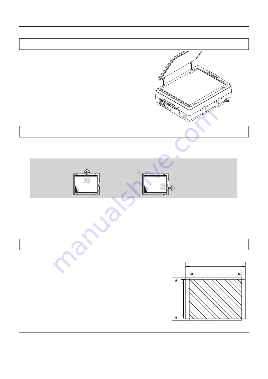
The maximum reading size of documents and printed mate-
rial is 216 mm high by 288 mm wide.
Consequently, when A4 paper (210 mm high and 297.5 mm 
wide) is placed on the projector, reading will be as illustrated 
in  the  diagram  below  (which  depicts  the  area  that  can  be 
projected as the portion with diagonal lines).

Attaching the Document Cover

The  mounting  orientation  of  the  document  cover  can  be 
changed  to  the  opposite  direction  in  accordance  with  the  cir-
cumstances circumstances.

Preparation of the Projection Document

The document (printed material) that is to be projected is placed on the projector as illustrated in the diagram be-
low and the document cover is closed.

NOTE:

•  The document can be projected even when the document cover has not been closed; however, in this instance, unnecessary 

items may be projected which will make the image difficult to view.

•  When shiny paper like magazine covers or black paper is placed on the projector, the internal fluorescent light bulb may be 

reflected in it, making the edges of the projected document hard to see.

Reading Size of Projection Documents

Other functions that are used in the OHP operation can be seen on the following pages:

 Switching the input to OHP 

 See Page E-23

 Changing the projection image to a still image display 

 See Page E-26

 Capturing a projection image 

 See Page E-26

 Viewing captured images 

 See Page E-27

NOTE: 

When removing the document cover, lift the cover by 

both hands and remove it.

Horizontal document  Top side

Vertical document
Top side

The  portion  that  falls  outside  of  the  reading  range  will  not  be  projected; 
therefore, shift the paper as required.

A4 Paper

297 mm (Paper size)

288 mm (Reading size)

216 mm (Reading size)

210 mm (Paper size)

Содержание iP-30

Страница 1: ...A Proposal for New Presentations Intelligent Projector User s Manual iP 30 English Deutsch Fran ais Espa ol Italiano...

Страница 2: ...anced technology inherent in the design Offers an easy fit when in use or when stored Expressive color pictures High resolution 4 130 000 pixel CCD camera is built in It provides faithful and clear re...

Страница 3: ...if you continue using the damaged power cable Do not peep into the lens Do not peep into the lens of the projector during operation The powerful rays passing through the lens could damage the eyes Do...

Страница 4: ...lass surface Take care not to scratch the glass surface of the scanner with hard or pointed objects Scratches on the glass may distort the projected image Battery When inserting battery in the remote...

Страница 5: ...ctor Doing so could cause the projector to roll over or break resulting in injury Especially be careful if small children are near Do not use the rack unless the casters are locked when placing the pr...

Страница 6: ...age E 22 Adjusting the Projection Image E 22 Making Focus Zoom Adjustments E 22 Adjusting the Tilt Slant E 22 Regular Operation E 23 Select the Input E 23 Changing the Orientation of the Projection Im...

Страница 7: ...e remote control iP 30 User s Manual PC connection cable 2 m No USB cable is included with the iP 30BE Pull out the sheet before use iP Viewer Software Quick Reference Only included with the iP 30SE U...

Страница 8: ...r printed material to be read is placed under this cover See Page E 30 Operation panel The buttons used for regular operation are located here See Page E 11 Air intake vent Air filter Air is drawn int...

Страница 9: ...IR sensor Document reading area The document or printed mate rial that you wish to project in the OHP mode is placed here See Page E 30 Power input connector Plug in the power cable here See Page E 21...

Страница 10: ...See pages E 16 and 20 3 S video input connector This input connector is for use with the Y C video See Page E 20 4 Video input connector This input connector is for use with the video NTSC PAL SECAM S...

Страница 11: ...f projection to standby Green Green Off Projecting Red Red Off Lamp cover open Power has been switched OFF because of the alarm Lamp burned out Lamp usage exceeds 2 000 hours Red Orange Off Internal p...

Страница 12: ...when the pointer is being dis played See Pages E 24 25 27 and 29 8 SET POINTER Button During menu display this button advances the menu to the next level This button finalizes the setting at the time...

Страница 13: ...been inserted for protection during transportation prior to shipping Please pull out and remove the sheet before use Insulation sheet Handling of the Remote Control Do not subject the remote control...

Страница 14: ...21 Switch Off the Power See Page E 21 4 Switch on the power of the personal computer or video equipment 5 Properly adjust the projection image to the screen See Page E 15 6 Select the input equipment...

Страница 15: ...200 200 200 250 300 300 350 Wide Tele inch Setup Location Do not place the projector in locations that will reach high temperatures or low temperatures Operation ambient temperature 0 C 32 F to 35 C...

Страница 16: ...e with a notebook computer and the image is displayed on the LCD screen of the notebook computer a proper display might not be obtained on projection screen Switching off the display of the notebook c...

Страница 17: ...DEO BLUE VIDEO GND NC Connecting Macintosh Computers When the monitor output is set to the VGA port mini D SUB 15 pin mount the PC connection cable included with the main unit An optional Apple video...

Страница 18: ...for Connection Problems with the Personal When the Image of the Personal Computer Screen Is Not Projected The screen of the personal computer is correct but the image is not projected properly Please...

Страница 19: ...ported NTSC RGB 15 7 60 No PAL SECAM RGB 15 6 50 No PC 98 Normal 1 640 400 24 8 56 Yes PC 98 Hi 640 400 31 5 70 Yes VGA GR1 640 480 31 5 60 Yes VGA GR2 1 640 400 31 5 70 Yes VGA GR3 1 640 350 31 5 70...

Страница 20: ...input signal When a condition in which a signal has not been input continues for 15 minutes or longer the lamp is turned off automatically This only functions when the auto power off mode is set to O...

Страница 21: ...cool the machine The projector is now able to make a projection 3 Switch on the power of the connected equipment CAUTION TE ST RG B S V L R AU DI O US B O N S TA N D BY LA M P C O VE R T E M P FR E E...

Страница 22: ...eight has been reached Rotating the lowest portion of the tilt foot permits fine adjustments to be made The tilt foot are lengthened by rotated to the left and shortened by rotated to the right O N S...

Страница 23: ...LAMP COVER TEMP FREEZE OFF FREEZE CAPTURE PORTRAIT INPUT POWER TRANSFER OHP This operation switches the vertical horizontal orientation of the currently projected image The display of the switched scr...

Страница 24: ...size of projected image The magnification can be adjusted from none to approximately 25x length ratio approx 5x when the input is set to OHP 16x length ratio approx 4x when the input is set to PC or...

Страница 25: ...om the main unit s control panel Operation with the Remote Control Adjust using the BRIGHTNESS buttons Projection image becomes brighter Projection image becomes darker To change the brightness perfor...

Страница 26: ...USB cable is not connected the icon s USB characters are not displayed The number of images that can be stored depends on the size of the image About 50 images of regular size can be stored Operation...

Страница 27: ...5 16 1 2 3 4 5 6 7 8 9 10 11 12 13 14 15 16 1 2 3 4 5 6 7 8 9 10 11 12 13 14 15 16 1 2 32 32 1 2 3 4 5 6 7 8 9 10 11 12 13 14 15 16 1 2 3 4 5 6 7 8 9 10 11 12 13 14 15 16 1 2 3 4 5 6 7 8 9 10 11 12 13...

Страница 28: ...the input is set to PC component video Press the PORTRAIT button When the input is set to OHP Use the input selec tor to select PC then press the PORTRAIT button button ON STANDBY LAMP COVER TEMP FRE...

Страница 29: ...oving the Pointer Operation with the Projector Scrolling is not possible from the main unit s control panel Operation with the Remote Control Press the SCROLL buttons See Page E 35 for information abo...

Страница 30: ...document cover has not been closed however in this instance unnecessary items may be projected which will make the image difficult to view When shiny paper like magazine covers or black paper is place...

Страница 31: ...wer off Lamp usage time Input signal PC input RGB Pointer shape Contrast Keystone Pointer color Brightness Language selection Pointer size Red Projection mode Mute mode Blue Economy mode Computer inpu...

Страница 32: ...m contents Names and Functions of the Menu Parts Menu tab Switches to the various menus when selected Adjustment bar Indicates the adjustment condi tion according to the increase or decrease of the ba...

Страница 33: ...an example 1 Press the MENU button and display the menu 2 Select Settings with the SCROLL buttons Each press of the SCROLL button switches the menu one step in the sequence of Pointer Screen Image ad...

Страница 34: ...while checking the projection im age SCROLL button Each press causes the numerical value to decrease The lower portion of the projection im age becomes narrower SCROLL button Each press causes the num...

Страница 35: ...uality Select the picture quality for saving OHP documents in the history Fine When this is selected the file size is large and fewer images can be stored but the picture quality is high Standard When...

Страница 36: ...leted and the next history image is displayed When a single image selected from the list of OHP history im ages is displayed the following item is also displayed Back page in history Next page in hist...

Страница 37: ...the numerical value increases the sharpness of the im age is enhanced Menu Description Image adjustment This performs the settings and adjustments related to the projected image When OHP input has be...

Страница 38: ...im age is enhanced Sub menu Video Select only valid when the input is set to VIDEO This selects the input signal system Auto detects the signal system automatically NTSC 3 58 NTSC 4 43 SECAM PAL B G...

Страница 39: ...appearance of a portion of the image Please see Page E 19 for details The keystone correction adjustment range will differ depending on the video signal system When the keystone adjustment is performe...

Страница 40: ...brightness of the lamp will be approximately 80 The lamp ser vice life will be extended OFF High brightness mode The brightness of the lamp will be 100 There will be a bright screen Auto power off Whe...

Страница 41: ...jector in an operation ambient temperature of 0 C 32 F to 35 C 95 F Are the ventilation vents blocked Rearrange the setup location of the projector and separate the projector from surrounding objects...

Страница 42: ...5 C 95 F Are the ventilation vents blocked Breakdown of an internal circuit could be the problem Please use the projector in an operation ambient tempera ture of 0 C 32 F to 35 C 95 F Rearrange the se...

Страница 43: ...indicated on the menu screen is the time calculated by converting the usage times in the high brightness and eco modes to the equivalent in the high brightness mode Because of this if you always use t...

Страница 44: ...out 4 Install a new lamp unit Take the lamp unit and press it into the projector Check that the two positioning prongs on the bottom of the lamp unit are securely fit into the two holes Tighten the 2...

Страница 45: ...and projection will start The power plug is plugged into a power outlet and only the ON STANDBY LED is lit red Do not reset the lamp usage time without replacing the lamp The likelihood of the lamp ru...

Страница 46: ...opposite order to attach Press the air filter A firmly in all the way to the back Press the air filter cover B in until a click is heard NOTE The air filter can be purchased together with the lamp uni...

Страница 47: ...5 E 39 E 8 The image flickers Please adjust Phase of the Sync adjustment menu E 38 T h e i m a g e i s o u t o f adjustment Are the settings of the Sync adjustment menu suitable E 38 The color is not...

Страница 48: ...prob lem contact the dealer where you bought the product When asking for repair service provide your dealer with the following information Description of the problem as many details as possible Date...

Страница 49: ...l Analog 0 7Vp p 75 Sync Signal Separate composite TTL Level positive negative Sync on green 0 3 Vp p Negative Terminal Panel 15 pin Mini D sub 1 ch Video Signal system NTSC PAL SECAM PAL N PAL M NTSC...

Отзывы: