


EX5000 Release 8.2.2 Installation Manual P/N 600-00073-001 Rev 02
- 49 -
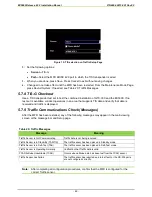
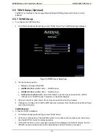
Figure 15: TIS selection on Traffic Setup Page
2.
Set the following options:
•
Sensor—
TIS-G
•
Port—
Select the MFD ARINC 429 port to which the TIS transponder is wired.
3.
When you are done, press
Save
. Press
Cancel
to exit without saving changes.
4.
Changes do not take effect until the MFD has been restarted. From the Maintenance Mode Page,
press
Restart System
. If needed, see Table 20: Traffic Messages.
5.7.8 TIS-G Checkout
Use a TIS transponder test set to test the combined installation of GTX-330 and the EX5000. If no
test set is available, conduct operations in an area that supports TIS data and verify that data is
received and traffic is displayed.
5.7.9 Traffic Communications Check (Messages)
After the MFD has been restarted, any of the following messages may appear in the main viewing
screen or the message bar and Setup page.
Table 20: Traffic Messages
Message
Meaning
Traffic Sensor is Not Communicating
Traffic data is not being received.
Traffic Sensor is in Stand-By (TAS/TIS)
The traffic sensor has been placed in Standby mode.
Traffic Sensor is in Self-Test (TAS)
The traffic sensor has been placed in Self-Test mode.
Traffic Sensor is Operating Normally
Verification that Traffic data is valid.
TCAD Altitude Unavailable (TCAD)
Occurs when altitude data has been lost from the TCAD sensor.
Traffic Sensor has Failed
The traffic sensor has reported an internal fault, or the RS-232 ports
are not configured correctly.
Note:
After completing all configuration procedures, confirm that the MFD is configured for the
correct Traffic sensor.
Содержание Entegra EX5000
Страница 1: ......
Страница 64: ...EX5000 Release 8 2 2 Installation Manual P N 600 00073 001 Rev 02 64 Save Configuration ...
Страница 95: ...EX5000 Release 8 2 2 Installation Manual P N 600 00073 001 Rev 02 95 Appendix G Landscape Cutout Dimensions ...
Страница 96: ...EX5000 Release 8 2 2 Installation Manual P N 600 00073 001 Rev 02 96 Appendix H Portrait Cutout Dimensions ...
Страница 98: ...EX5000 Release 8 2 2 Installation Manual P N 600 00073 001 Rev 02 98 Appendix J Wiring Diagram GPS FMS ...
Страница 99: ...EX5000 Release 8 2 2 Installation Manual P N 600 00073 001 Rev 02 99 ...
Страница 101: ...EX5000 Release 8 2 2 Installation Manual P N 600 00073 001 Rev 02 101 Appendix L Wiring Diagram Traffic Sensors ...
Страница 102: ...EX5000 Release 8 2 2 Installation Manual P N 600 00073 001 Rev 02 102 Appendix M Wiring Diagram TAWS ...
Страница 103: ...EX5000 Release 8 2 2 Installation Manual P N 600 00073 001 Rev 02 103 Appendix N Wiring Diagram Radar Sensor ...
Страница 104: ...EX5000 Release 8 2 2 Installation Manual P N 600 00073 001 Rev 02 104 Appendix O Wiring Diagram Engine Sensors ...