background image

Chapter 4: Detaching Chassis 

18

Removing the Bolster

Remove the Bolster (arm rest) by unscrewing its fasteners and lifting it off the front edge of the frame. 

To remove the Bolster: 

1

From underneath the Bolster, remove all Hex fasteners that secure it to the frame. 

2

Pick up the Bolster using both hands. With Bolsters for larger systems (six or more chassis in width), get someone to help.

3

Lift the Bolster out of the receiving edge along the top-front edge of the frame, and set it aside. 

Expanding a Bolster

If you are adding one or more chassis to an existing system, you must also expand the Bolster. The Bolster can be expanded by add-
ing an additional Bolster (two chassis in width, minimum) and combining it with the existing Bolster, or by replacing the existing 
Bolster with a single new, larger Bolster. The way in which you can expand your Bolster is determined by the number of chassis 
you are adding, and by the date that your system shipped from the factory. 

• If you are adding two or more chassis, you can either add an additional Bolster extension or completely replace the existing 

Bolster.

• If you are adding a single chassis to a Leg Frame system, or if your system shipped from the factory before July 2, 2014, you 

must replace your existing Bolster. In addition, if your system shipped before July 2, 2014, you might also have to upgrade 
your Extrusions (Beams) and Side Covers. 

Contact your Avid S6 dealer, or Avid Customer Care for more information. 

Have someone hold the Bolster in place while you remove the fasteners to prevent it from falling on you. 

Figure 12. Removing the Bolster

(Not to scale)

M5x10 BHCS (7760-30615-00)

Fastener

M3 Hex

Tool

Содержание Pro Tools S6 Master Post Module

Страница 1: ...Expanding an S6 System ...

Страница 2: ...00 Lo Fi MachineControl Magic Mask Make Anything Hollywood make manage move media Marquee MassivePack MassivePack Pro Maxim Mbox Media Composer MediaFlow MediaLog MediaMix Media Reader Media Recorder MEDIArray MediaServer MediaShare MetaFuze MetaSync MIDI I O Mix Rack Moviestar MultiShell NaturalMatch NewsCutter NewsView NewsVision Nitris NL3D NLP NSDOS NSWIN OMF OMF Interchange OMM OnDVD Open Med...

Страница 3: ...moving Display Modules 9 Removing T Strips 9 Removing Compression Panels and Fill Panels 10 How to Proceed 10 Chapter 3 Removing Modules and Disconnecting Cabling 11 Removing Modules 11 Disconnecting Cable Sets 12 Chapter 4 Detaching Chassis 13 Determine Which Chassis to Detach 13 Disassembling a Frame 16 How to Proceed 21 Chapter 5 Disassembling and Expanding Leg Frames 22 Guidelines for Leg Fram...

Страница 4: ...Part I Introduction ...

Страница 5: ...32 or more faders to avoid risk of damage to the frame If you need to move a five chassis or wider S6 system that does not include Legs you must par tially disassemble the frame so that no section is more than four chassis in width If your system does include Legs partially disassemble the frame so that no section is more than four chassis in width and remove those sections from the leg frame Also...

Страница 6: ...ons in this guide to determine where and how to disassemble the frame Expanding a System with Additional Modules or Chassis S6 systems can be disassembled to expand the system by adding or rearranging modules or by adding chassis You can add Display Modules to M40 systems not M10 at any time up to the capacity of the frame one per channel section You can add additional modules to expand a system i...

Страница 7: ... page Click a symbol to expand that heading to show subheadings Click the symbol to collapse a subheading The Table of Contents provides active links to their pages Select the hand cursor allow it to hover over the heading until it turns into a finger Then click to locate to that subject and page All text and cross references in blue are active links Click to follow the reference Select Find from ...

Страница 8: ... Com patibility documents for system requirements search the online Knowledge Base or join the worldwide Avid user community on the User Conference https www avid com Support index html Knowledge Base for S6 downloads http avid force com pkb articles faq Avid S6 Support Training and Education Study on your own using courses available online or find out how you can learn in a classroom setting at a...

Страница 9: ...Part II Disassembly ...

Страница 10: ...ving If the Master Module is being removed drag blank strips over all channel sections and then replace the Master Module section with only the Master Module no Automation Module 4 Press Next 5 In the next screen drag blank strips over Display Modules if any then press Next Temporarily Unclaiming a Module If you forget to remove a module from the surface arrangement before physically moving it to ...

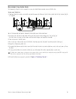
Страница 11: ...omponents We recommend removing all upper Rear Covers To remove the upper Rear Covers 1 Standing at the back of the system start at the far right see Figure 1 2 Loosen the thumbscrews that hold the upper covers to their mounting brackets and then lift the covers off Disconnecting Power Cables and Removing the Power Strip To remove the power strip 1 Unplug the power strip from its source 2 Disconne...

Страница 12: ... the four fasteners that secure the first Display Module to its mounting bracket 3 Set the Display Module s face down on a flat surface Removing T Strips To remove T strips Remove the T strips from between chassis one at a time Start at the top back of the control surface and use a small flat head screwdriver to push down on the tab that holds the T strip in place then lift the strip out Figure 2 ...

Страница 13: ... the back of the console to com press their built in springs then lift out the front edge and remove the panel To remove Fill Panels Lift Fill Panels out of their slots How to Proceed After completing the disassembly instructions in this chapter proceed to Chapter 3 Removing Modules and Disconnecting Cabling Figure 4 Removing a Channel Compression Panel left and a Master Compression Panel right ...

Страница 14: ...wing 1 Make sure you have a padded tabletop or other flat surface to place each module as it is removed Try to arrange removed mod ules in the same order and relative positions as they are in the assembled system to simplify reinstalling them later 2 If your system includes Display Modules remove them first see Removing Display Modules on page 9 and place them on the table face down 3 Beginning wi...

Страница 15: ... Cable Set aside 4 Move to the next chassis disconnect its Cable Set then disconnect the other ends from their network switch ports 5 Repeat for all remaining Cable Sets 6 Disconnect the Ethernet cable s that connect the S6 network switch to external workstations or networks and remove it from the frame 7 If your system includes two network switches be sure to disconnect the cable connecting them ...

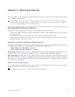
Страница 16: ...gurations on page 15 Moving a System The frame only needs to be disassembled when it is five or more chassis in width Never attempt to move a frame or section of a frame of five or more chassis Diagrams for these size chassis begin with 5 Chassis on page 14 Expanding a System To expand a frame it is more efficient to add new chassis within the frame instead of adding them to the far right or far l...

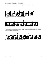
Страница 17: ...s 3 Chassis 4 Chassis 5 Chassis The following diagrams do not show cable harnesses Rear Cover brackets Side Covers or the Producers Desk option If your system includes a Producers Desk it counts as two chassis when determining system width Where to detach chassis to expand a two chassis frame Where to detach chassis to expand a three chassis frame Where to detach chassis to expand a four chassis f...

Страница 18: ...s systems require two pairs of chassis to be detached before moving We recommend detaching where indicated in Figure 8 to minimize the weight of all sections Figure 6 Where to detach chassis to move or expand a six chassis frame Figure 7 Where to detach chassis to move or expand a seven chassis frame Figure 8 Where to detach chassis to move or expand a nine chassis frame 1 2 3 4 5 6 1 2 3 4 5 6 7 ...

Страница 19: ...and one on the right end of the Bolster then remove each fastener 2 From the inside of the chassis remove the four Phillips screws that secure the Side Cover to the frame see Figure 10 As you disassemble frame components keep all fasteners organized to simplify re assembly To simplify fastener organization print the pages of Appendix A Labels for Fasteners and cut out the labels provided for each ...

Страница 20: ... Leg Frame system or if your system desktop or Leg Frame shipped from the factory before July 2 2014 you must replace your existing Bolster In addition if your system shipped before July 2 2014 you might also have to upgrade your Side Covers Contact your Avid S6 dealer or Avid Customer Care for more information Figure 11 Removing the right Side Cover Not to scale M4x14 FHPH Fastener 2 Phillips Too...

Страница 21: ...ing Bolster or by replacing the existing Bolster with a single new larger Bolster The way in which you can expand your Bolster is determined by the number of chassis you are adding and by the date that your system shipped from the factory If you are adding two or more chassis you can either add an additional Bolster extension or completely replace the existing Bolster If you are adding a single ch...

Страница 22: ...rs aside 4 Repeat for any additional Rear Cover Mounting Brackets you need to remove Removing One or More Back Feet Remove the Back Foot attached to each pair of chassis to be detached Remove any hardware options such as a SpeakerDeck or VESA Mount attached to the Back Foot you will be removing To remove a Back Foot 1 Using a 2 Phillips screwdriver remove the four screws that secure the Back Foot ...

Страница 23: ... by carefully lifting the chassis or section to the left when standing in front of the frame up and away from the chassis or section to the right 5 Repeat for any other chassis that need to be detached Figure 15 Removing the fasteners that secure the Side Wall of one chassis to the Back and Front Tie Plates of another On some early systems the Ethernet Switch Tie down Bracket might need to be remo...

Страница 24: ... the Module layout and the new width of your frame This determines switch and PSU placement and cabling requirements 2 Re assemble Legs if any re attach and or add new chassis then reinstall Rear Covers reinstall or replace Side Covers and Bolster and other frame components 3 If necessary install new or move existing Ethernet switch es and or PSUs 4 Install Cable Sets modules and other hardware co...

Страница 25: ...be detached from each other before lifting or moving Larger Leg Frames might need to be fully disassembled detach Beams from Legs before they can be moved depending on the distance being moved the weight of the frame and the size of doorways or other obstacles If you are expanding a Leg Frame with one or more Leg Frame Extensions or adding a Leg Frame Join Module and additional Leg Frame s the fra...

Страница 26: ...re adding one or more Leg Frame Extensions to an existing Leg Frame you only need to remove one or both End Brackets To remove the End Brackets Remove the eight fasteners and washers per bracket that attach the Left and Right End Brackets to the Legs see Figure 19 Figure 18 Detaching the left frame from the Center Bracket Figure 19 Removing the right side End Bracket left side End Bracket shown at...

Страница 27: ... existing Bolster with a single new larger Bolster The way in which you can expand your Bolster is de termined by the number of chassis you are adding and by the date that your system shipped from the factory If you are adding two or more chassis you can either add an additional Bolster extension or completely replace the existing Bolster If you are adding a single chassis or if your system shippe...

Страница 28: ...Beam by removing the four fasteners and washers per bracket Removing the Front and Back Beams If you are disassembling the Leg Frame to move or expand it remove the Beams To remove the front Beam 1 Remove the four fasteners and washers per mount that secure the front Beam to the Legs then lift the Beam off of the Legs see Figure 22 If your Leg Frame is an original early 2014 unit remove the fasten...

Страница 29: ...ble Sets modules and other hardware components Refer to the S6 Installation Guide for step by step instructions To expand a system 1 Follow instruction in the S6 Installation Guide to determine the Module layout and the new width of your frame This determines switch and PSU placement and cabling requirements 2 Re assemble Legs if any re attach and or add new chassis then reinstall Rear Covers rein...

Страница 30: ...Part III Appendix ...

Страница 31: ...ide Covers to Chassis Rear Cover Mounting Brackets Back Feet Fastener Tool M4x10 BCHS M2 5 Hex Not to scale M5x10 BHCS 7760 30615 00 Fastener M3 Hex Tool 7760 30535 00 Not to scale M4x10 BCHS Fastener M2 5 Hex Tool Not to scale M4x14 FHPH 7760 30622 00 Fastener 2 Phillips Tool 7760 30535 00 Plug 7600 31532 01 Not to scale M5x8 SHCS 7760 30593 00 Fastener M5 WSHR Washer M4 Hex Tool Not to scale M5x...

Страница 32: ...3 Hex Tool Not to scale M3x6 SEMS 7760 30025 01 Fastener 1 Phillips Tool Not to scale M5x15 7760 30604 00 Fastener M5 WSHR 7760 30607 00 Washer M4 Hex Tool Not to scale M5x15 7760 30604 00 Fastener M5 WSHR 7760 30607 00 Washer M4 Hex Tool Not to scale M8x30 7760 30606 00 Fastener M8 WSHR 7760 30609 00 Washer 6mm Hex Tool Not to scale M5x15 7760 30604 00 Fastener M5 WSHR 7760 30607 00 Washer M4 Hex...

Страница 33: ......

Страница 34: ...Bernardo Avenue Mountain View CA 94043 USA Technical Support USA Visit the Online Support Center at www avid com support Product Information For company and product information visit us on the web at www avid com ...

Отзывы: