AVG-UDATP4
4.4. Connection Procedure
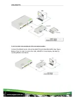
Step 1. Connect an HDMI source device (e.g. Blu-ray DVD) to the HDMI INPUT
socket of the AVG-UDATP4 with an HDMI cable.
Step 2. Connect an HDMI display to HDMI OUTPUT socket of AVG-UDATP4 with
an HDMI cable.
Step 3. Connect AVG-HD402PR(s) to HDBT output port(s) of AVG-UDATP4 with
twisted pair.
Step 4. Connect control device (e.g. PC) to the RS232 IN port of AVG-UDATP4 or
AVG-HD402PR (bi-directional RS232 control, either end is available).
If you want to cascade RS232 signals among several AVG-UDATP4 units
through the RS232 LOOP, connect the RS232 LOOP socket of one of
them and the RS232 IN socket of the next until all the AVG-UDATP4 units
have been connected.
Step 5. Connect an IR Receiver to the IR IN port, and an IR Emitter to the IR OUT
port. The IR signal can be transmitted bi-directionally between AVG-
UDATP4 and AVG-HD402PR(s).The IR signal is 5volt.
If you want to cascade the IR signal among several AVG-UDATP4 units,
connect the IR LOOP socket of one of them and the IR IN socket of the
next until all the AVG-UDATP4’s have been connected.
Step6.
Connect a DC 24V power adapter to the power port of the AVG-UDATP4,
the AVG-HD402PR is able to be powered by the AVG-UDATP4 using the
PoC capability that is built in.
4.5. Cascade Connection
4.5.1. Cascade AV Signal
HDMI source signals can be cascaded to several displays via HDMI OUT/ IN.
Connect the HDMI OUT socket of the first AVG-UDATP4 to the HDMI IN socket of
the next until all AVG-UDATP4 units have been connected.
HDMI signals connected to the first AVG-UDATP4 are able to be output to
other connected AVG-UDATP4 units as well.
4.5.2. Cascade Control Signal
The AVG-UDATP4 supports control cascading via IR LOOP/ RS232 LOOP to
enable signal loop output. Users can choose one or multiple cascade methods
according to their specified needs.
Содержание AVG-UDATP4
Страница 20: ...AVG UDATP4 7 Panel Drawing ...


