

19
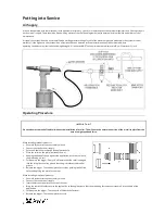
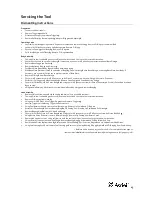
Priming
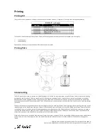
Initial Priming Procedure
Follow these instructions if all of the oil has been emptied from the tool, e.g. following tool disassembly and maintenance. If the tool has stroke
loss, follow the Top-up Priming Procedure on page 20.
Follow the Hyperlink below or alternatively scan the QR-code for a video of the Initial priming procedure for this tool.
http://youtu.be/k4g9iT4hhI8
*Bullet numbering below relates each step to relevant section of the priming video
Preparation
①
Ensure tool is disconnected from air supply.
①
Remove all bleed screws
1
and seals
5
.
①
Using soft jaws to hold the tool Handle, position the tool in the nose-down orientation.
Pull side priming
①
Ensure tool is disconnected from air supply.
①
Remove all bleed screws before priming.
①
Using a 27mm A/F spanner and the Return Stroke Setter*, ensure that the Head Piston
64
is fully forward. Remove Return Stroke Setter.
①
Fit Extension* to one Priming Syringe*.
①
Fill both Priming Syringes* with approximately 30ml of oil and remove any air from the syringes.
①
Fit Priming Syringe* to lower pull bleed port.
①
Fit Priming Syringe* with Extension* to upper pull bleed port.
②
Push oil from the first syringe until no air bubbles are evident in the second syringe, or until the oil drops below 5ml.
②
Push oil from the second syringe until no air bubbles are evident in the first syringe, or until the oil drops below 5ml.
②
Repeat previous 2 steps until no air bubbles are evident.
②
Even out oil volumes between each syringe. Including oil and air, the plunger must not be above 25ml volume in either syringe.
③
Connect tool to air supply.
③
Press and hold Trigger. This ensures the Air Piston
33
is at the end of the pull stroke.
③
Disconnect tool from air supply.
④
Remove the Priming Syringe* from the lower pull bleed port and reseal this port.
⑤
Using a 27mm A/F spanner and both sides of the Pull Stroke Setter*, wind the Head Piston
64
back to 21mm stroke, applying pressure to
the plunger at all times. This ensures that no air is drawn into the system as the Head Piston is pushed back.
⑥
With the Head Piston at 21mm stroke, remove Pull Stroke Setter.
⑦
Remove the Priming Syringe* with Extension* and reseal this port.
Return side priming
⑦
Ensure tool is disconnected from air supply.
⑦
Ensure Extension* is fitted to one Priming Syringe*.
⑦
Fill both Priming Syringes* with approximately 30ml of oil and remove any air from the syringes.
⑦
Fit Priming Syringe* to return bleed port.
⑦
Fit Priming Syringe* with Extension* to second return bleed port.
⑧
Push oil from the first syringe until no air bubbles are evident in the second syringe, or until the oil drops below 5ml.
⑧
Push oil from the second syringe until no air bubbles are evident in the first syringe, or until the oil drops below 5ml.
⑧
Repeat previous 2 steps until no air bubbles are evident.
⑧
Even out oil volumes between each syringe. Including oil and air, the plunger must not be above 25ml volume in either syringe.
⑨
Connect tool to air supply. This ensures the Air Piston
33
is at the end of the return stroke.
⑨
Disconnect tool from air supply.
⑩
Remove Priming Syringe* fitted with Extension* and reseal this port.
⑩
Using a 27mm A/F spanner, Starter Nut and both sides of the Return Stroke Setter*, wind the Head Piston
64
forward to 0mm stroke,
applying pressure to the plunger at all times. This ensures that no air is drawn into the system as the Head Piston is drawn forward.
⑪
With the Head Piston fully forward, apply reasonable pressure to the plunger to push oil from the syringe up to a stop. Approximately 0.5ml
will be pushed from the syringe into the tool.
⑪
Remove Return Stroke Setter.
⑪
Remove the Priming Syringe* and reseal this port.
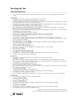
Pull and return test
⑫
Measure the distance from the end of the Head Piston
64
to the front of the Head
63
.
⑫
Connect tool to air supply.
⑫
Cycle the tool. Measure the distance from the end of the Head Piston to the front of the Head. Ensure the Head Piston stroke is 21mm and
that Head Piston fully returns at the end of the cycle. If not, follow the Top-up Priming Procedure on page 20.
⑫
Disconnect tool from air supply. The tool is now primed.
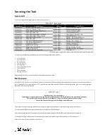
* Refers to items included in 73200 Service Kit. For complete list see page 12.
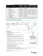
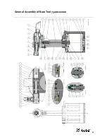
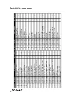
Item numbers in
bold
refer to the General Assembly drawing and parts list (pages 15 – 16).
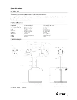
Содержание 73200 Tool
Страница 1: ...Instruction Manual Original Instruction 73200Tool Hydro Pneumatic PowerTool ...
Страница 2: ...2 ...
Страница 15: ...15 General Assembly of BaseTool 73200 02000 ...


