13
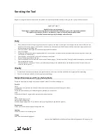
Servicing the Tool
Dismantling Instructions
Preparation
•
Connect tool to air supply.
•
Depress Trigger
29
and hold.
•
Disconnect air supply and release Trigger
29
.
•
Remove Deflector
47
, Retaining Nut
49
, Adaptor Ring
50
and Adaptor
48
.
Operating Valve
•
Unscrew Swivel Bolt
44
using 22mm A/F spanner or socket and remove Swivel
43
. Remove 'O' Rings
4
from Swivel Bolt.
•
Use 6mm A/F Allen key to remove Valve Retainer
40
. Remove 'O' Ring
7
.
•
Push Valve Spool
39
out of Body
65
. Remove 'O' Rings
11
.
•
Pull Valve Body
42
out of Body
65
. Remove 'O' Rings
10
and
11
.
Body Assembly
•
Fit Head Vice Jaw* to Head
63
and use soft jaws to hold the Head Vice Jaw in the inverted orientation.
•
Use Locknut Socket* to unscrew Locknut
38
. If necessary, use a 10mm A/F Allen key to prevent rotation of Base Plate
32
.
•
Remove Base Cap
31
and Gasket
36
.
•
Remove Retaining Ring
25
and Silencer
37
.
•
Push Base Plate
32
into Body
65
and remove Retaining Ring
24
.
•
With Base Plate extractor* fitted to underside of Body
65
, screw Locknut
38
onto Base Plate
32
, extracting Base Plate from Body. If
necessary, use a 10mm A/F Allen key to prevent rotation of Base Plate.
•
Remove 'O' Ring
8
from Base Plate
32
.
•
Fit 14mm A/F spanner or 5mm A/F Allen key on to Air Piston Connector
41
. Unscrew Nut
3
with 27mm A/F spanner.
•
Extract Air Piston
33
using M6 threaded holes. Remove Quad Seal
9
and Force Reduction Seal
35
.
•
Fit 4mm A/F Allen key into Air Piston Rod
58
and using 14mm A/F spanner unscrew Air Piston Connector
41
. Push Air Piston Rod into Head
63
up to stop.
•
Using Handle Retaining Nut Wrench* unscrew Handle Retaining Nut
34
and remove Body
65
.
Head Assembly
•
Remove 4 Bleed Screws
1
and Bonded Seals
5
and drain oil into a suitable container.
•
Fit Head Vice Jaw* to Head
63
and use soft jaws to hold the Head Vice Jaw in the inverted orientation.
•
Remove 'O' Rings
13
from Head
63
.
•
Using a 2mm Pin Punch* drive Trigger Pin
30
out and remove Trigger
29
.
•
Unscrew Trigger Valve
28
using Trigger Valve Extractor*.
•
Using Seal Retainer Wrench* remove Seal Retainer
55
. Remove Lip Seal
16
and 'O' Ring
12
.
•
Extract Air Piston Rod
58
. Remove Bearing Ring
62
, Lip Seal
15
, Seal Stop
61
, Lip Seal
14
and Pull Piston
56
.
•
Remove Bearing Ring
60
from Air Piston Rod End
59
.
•
Fit 4mm A/F Allen key into Air Piston Rod
58
and using 14mm A/F spanner or 5mm A/F Allen key unscrew Air Piston Rod End
59
.
•
Using Return Piston Extractor* remove Return Piston
57
. Remove Lip Seal
14
from Return Piston.
•
Remove the Head Vice Jaw*. Using soft jaws to hold the tool Handle, position the tool in the nose-down orientation.
•
Using 48mm A/F spanner unscrew End Cap
51
. Remove Bearing Ring
53
, Wiper
22
and 'O' Ring
6
from End Cap.
•
Remove Head Piston
64
from Head
63
. Remove Head Piston Seals
19
, Anti-extrusion Rings
20
and Lip Seal
21
from Head Piston.
•
Using Seal Housing Push Rod* remove Seal Housing
52
. Remove Lip Seal
17
, Bearing Ring
54
, Wiper
18
and 'O' Ring
23
from Seal Housing.
* Refers to items included in 73200 Service Kit. For complete list see page 12.
Item numbers in
bold
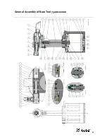
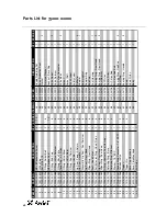
refer to the General Assembly drawing and parts list (pages 15 – 16).
Содержание 73200 Tool
Страница 1: ...Instruction Manual Original Instruction 73200Tool Hydro Pneumatic PowerTool ...
Страница 2: ...2 ...
Страница 15: ...15 General Assembly of BaseTool 73200 02000 ...


