SAFETY, INSTALLATION AND OPERATION MANUAL
AVANCIS POWERMAX
®
PHOTOVOLTAIC MODULES
13
©2021 | AVANCIS GmbH | Solarstraße 3 | 04860 Torgau | Germany | [email protected] | www.avancis.de | February 2021
Grounding of Back Rails
Even when applicable regulations, code
requirements and standards do not re-
quire safety-related grounding, AVANCIS
strongly recommends grounding of the
PV module back rails in order to ensure
voltage between back rails and ground
is zero volts under all circumstances. This
will increase the safety of the PV system
in case of malfunctions and protect the
system from induced over-voltage. For
safety-related grounding of the mod-
ule back rails, the back rails are provid-
ed with grounding holes (marked with
grounding signs). These holes should
be used for grounding purposes only
and in accordance with the local regula-
tions, code requirements and standards.
If permitted, AVANCIS recommends for
grounding to use the grounding holes in
combination with a screw, nut and two
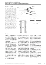
lock washers (see figure 1). Please note:
only materials should be used which
do not cause corrosion. Make sure that
the grounding screws do not touch any
cable. Other means and methods for
grounding are permissible as long as they
meet the applicable regulations, code re-
quirements and standards.
Mounting
• Permanent or recurring complete or al-
most complete shading of a small num-
ber of cell stripes (parallel to the long side
of the module), e.g., by ledges, sheath-
ings or poles, must be avoided. The op-
eration of an AVANCIS module under
such conditions leads to yield losses and
can permanently damage the partially
shaded module.
• The PV modules must be mounted to
the mounting lip on the back of the back
rails using 4 SMART clamps available
from AVANCIS. One SMART clamp holds
2 PV modules, except for the modules at
the beginning and end of a module row.
The SMART clamps shall only be mount-
ed as shown in figure 3.
• In order to install a second module, make
sure that the clamps are placed over the
mounting lip of the first module and
slide the second module towards the first
module. The mounting lip of the second
module will automatically lift the clamp
and the clamp will go down after the
mounting lip of this module is also under
the clamp. Finally, fasten the clamp once
the second module has been positioned
correctly.
• The glass edges of the two modules
must not touch during installation as this
can result in the glass breaking.
Fig. 1
Grounding of back rails
Screw
Nut
Lock washer
Back rail
Lock washer
Grounding cable
• All other parts such as screws, nuts etc.
are provided by the customer.
• Installation within Germany: For fas-
tening the clamps to the substructure,
M8 screws made of stainless steel FK70
according to Z-30.3-6 (Erzeugnisse,
Verbindungsmittel und Bauteile aus
nichtrostenden Stählen, Informations-
stelle Edelstahl Rostfrei) must be used.
These are suitable for the permanent use
in a PV system.
• Installation outside Germany: For fas-
tening the clamps to the substructure,
stainless steel screws must be used in ac-
cordance with national requirements for
the permanent operation of a PV system.
• The full length of the SMART clamps
must be in contact with the permitted
mounting zone of the back rails (marked
in gray in figure 2) and need to be fas-
tened with a torque of 20 Nm. The per-
mitted mounting zone comprises the full
length of the mounting lip of a back rail
with the exclusion of the first 6 cm, mea-
sured from the outer end. The permitted
mounting zone therefore covers the re-
gion between 264 mm and 633 mm as
measured from the outer glass edge (see
figure 3).
• The optimal position of the SMART
clamps is located in the middle of each
mounting lip of the back rail and it is rec-
ommended for mounting by AVANCIS
(figure 2). This provides the maximum sta-
bility against mechanical stresses. If there
is a deviation from the middle position,
the German general building approval
Z-70.1-224 has to be considered regard-
ing the resilience (at least in Germany).
Further information can be obtained
from AVANCIS or the DIBt (Deutsches
Institut für Bautechnik).
• The four clamps must be positioned
symmetrically on the four mounting lips,
both with respect to the center of the
module parallel to its long edge and to
its short edge.
• The modules can be installed both in
portrait and landscape format. The per-
missible inclination to the vertical can be
between 0° and 90°.
• A usage of the PV modules as overhead
glazing requires an assessment of the lo-
cal regulations and building codes.
• The mounting structure must be paral-
lel to the short side of the module and
therefore perpendicular to the back
rails. Other orientations of the mounting
structure are not permitted.
Fig. 3
Mounting of a SMART clamp
Fig. 2
Module rear side
60
60
264
633
Содержание POWERMAX
Страница 1: ...AVANCIS POWERMAX PHOTOVOLTAIC MODULES SAFETY INSTALLATION AND OPERATION MANUAL DEUTSCH ENGLISH ...
Страница 3: ...AVANCIS POWERMAX PHOTOVOLTAIK MODULE SICHERHEITS INSTALLATIONS UND BETRIEBSHANDBUCH DEUTSCH ...
Страница 9: ...ENGLISH AVANCIS POWERMAX PHOTOVOLTAIC MODULES SAFETY INSTALLATION AND OPERATION MANUAL ...

