background image

Quick  Reference  Guide 

SID-15WR1  Quick  Reference  Guide    9 

Construction 

Metal 

Color 

Black 

Dimension 

391.2 x 239.2 x 48.1mm 

Weight 

3.59 kg 

Fanless 

Yes   

IP Rating   

Front IP65 

Reliability 

EMI Test 

CE/FCC Part 15, Subpart B   

Safety 

IEC-60950-1 & EN 60950-1 

Dust and Rain Test 

Front Panel IP65 

Random Vibration 

Test 

Test Standard: Reference IEC60068-2-64 Testing procedures 

1.  System condition: Operation mode 

2.  PSD: 0.00454G²/Hz , 1.5 Grms 

3.  Test Frequency : 5-500Hz 

4.  Test Axis : X,Y and Z axis 

5.  Test time: 30 minutes per each axis 

6.  Storage : eMMC 

Sine Vibration Test 

(Non-operation) 

Test Standard: Reference IEC60068-2-6 Testing procedures 

1.  System condition : Non-Operating mode 

2.  Test Acceleration : 2G 

3.  Test frequency : 5~500 Hz 

4.  Sweep

1 Oct/ per one minute. (logarithmic) 

5.  Test Axis : X,Y and Z axis 

6.  Test time :30 min. each axis 

Packing Vibration 

Test 

Test Standard: Reference IEC60068-2-64 Testing procedures 

1.  Non-operation mode 

2.  PSD: 0.026G²/Hz , 2.16 Grms 

3.  Test Frequency : 5-500Hz 

4.  Test Axis : X,Y and Z axis 

5.  Test time: 30 min. per each axis 

Mechanical Shock 

Test 

Test Standard: Reference IEC60068-2-29 Testing procedures 

1.  System Condition: Operation 

2.  Wave form: Half-Sine wave 

3.  Acceleration: Rate: 10g 

4.  Duration: Time: 11ms 

5.  No. of Shock: Z axis 300 times 

6.  Test Axis: Z axis 

Packing Drop Test 

Reference ISTA 2A, Method: IEC-60068-2-32 Test:Ed 

1.  Test Phase: One comer, three edges, six faces 

2.  Packing weight: around 1.5kg 

Содержание SID-15WR1

Страница 1: ...rt No E2017S5R1A1R SID 15WR1 15 6 Panel PC with Rockchip RK3288 SoC 2G RAM 16G eMMC Quick Reference Guide 2nd Ed 27 September 2021 Copyright Notice Copyright 2021 Avalue Technology Inc ALL RIGHTS RESERVED ...

Страница 2: ...ere is no guarantee that interference will not occur in a particular installation If this equipment does cause harmful interference to radio or television reception which can be determined by turning the equipment off and on the user is encouraged to try to correct the interference by one or more of the following measures Reorient or relocate the receiving antenna Increase the separation between t...

Страница 3: ...tandard of your particular country WARNING To avoid risk of electric shock this equipment must only be connected to a supply mains with protective earth Notice This guide is designed for experienced users to setup the system within the shortest time For detailed information please always refer to the electronic user s manual Copyright Notice Copyright 2021 Avalue Technology Inc ALL RIGHTS RESERVED...

Страница 4: ...onably expected to cause the failure of the life support device or system or to affect its safety or effectiveness A Message to the Customer Avalue Customer Services Each and every Avalue s product is built to the most exacting specifications to ensure reliable performance in the harsh and demanding conditions typical of industrial environments Whether your new Avalue device is destined for the la...

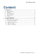
Страница 5: ...1 2 Packing List 6 1 3 System Specifications 8 1 4 System Overview 11 1 4 1 I O View 11 1 5 System Dimensions 12 2 Hardware Configuration 13 2 1 SID 15WR1 connector mapping 14 2 1 1 Serial port connector COM 14 2 1 2 RJ 45 Ethernet connector LAN 14 2 1 3 HDMI connector HDMI 15 2 1 4 USB2 0 connector USB2 0 15 ...

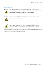
Страница 6: ...s Only experienced electronics personnel should open the PC chassis Caution Always ground yourself to remove any static charge before touching the CPU card Modern electronic devices are very sensitive to static electric charges As a safety precaution use a grounding wrist strap at all times Place all electronic components in a static dissipative surface or static shielded bag when they are not in ...

Страница 7: ... by an Incorrect Type Dispose of Used Batteries According to the Instructions Warning For RTC battery current statement in the manual is acceptable There is danger of explosion if the battery is mishandled or incorretly replaced Replace only with the same type of battery Do not disassemble it or attempt to recharge it outside the system Do not crush puncture dispose of in fire short the external c...

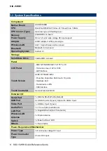
Страница 8: ...anel LCD Panel BOE NV156FHM N42 15 6 TFT LCD 16 9 wide screen 1920 x 1080 eDP Interface Touch Screen ACDC DY1562W 4262 Projective Capacitive Multi touch 10 points Hardness 6H Transmission 85 USB Interface Touch Controller Silicon Works SW4101D External I O Serial Port 1 x DB9 for RS 232 Tx Rx Default USB Port 2 x USB 2 0 ports Type A Option 3th USB 2 0 port Video Port 1 x HDMI 2 0 port Type A Audi...

Страница 9: ...8 2 6 Testing procedures 1 System condition Non Operating mode 2 Test Acceleration 2G 3 Test frequency 5 500 Hz 4 Sweep 1 Oct per one minute logarithmic 5 Test Axis X Y and Z axis 6 Test time 30 min each axis Packing Vibration Test Test Standard Reference IEC60068 2 64 Testing procedures 1 Non operation mode 2 PSD 0 026G Hz 2 16 Grms 3 Test Frequency 5 500Hz 4 Test Axis X Y and Z axis 5 Test time ...

Страница 10: ...de 3 Test high 96 5cm Based on product weight Operating Temperature 0 C 40 C 32 F 104 F Operating Humidity 40 C 95 Relative Humidity Non condensing Storage Temperature 20 C 60 C 4 F 140 F Note Specifications are subject to change without notice ...

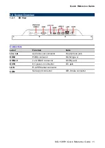
Страница 11: ... 1 4 1 I O View Connectors Label Function Note Line out Audio line out connector Head phone jack HDMI HDMI connector HDMI type A USB2 0 2 x USB2 0 connector USB type A DCIN DC power in connector DC jack LAN RJ 45 Ethernet connector COM Serial port connector DB 9 male connector ...

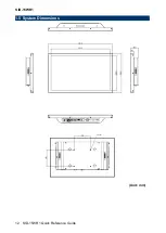
Страница 12: ...SID 15WR1 12 SID 15WR1 Quick Reference Guide 1 5 System Dimensions Unit mm ...

Страница 13: ...Quick Reference Guide SID 15WR1 Quick Reference Guide 13 2 Hardware Configuration Note If you need more information please visit our website http www avalue com tw ...

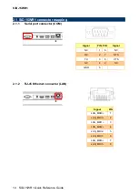
Страница 14: ...WR1 connector mapping 2 1 1 Serial port connector COM Signal PIN PIN Signal NC 1 6 NC RX 2 7 RTS TX 3 8 CTS NC 4 9 NC GND 5 2 1 2 RJ 45 Ethernet connector LAN Signal PIN LAN_MDI0 1 LAN_MDI0 2 LAN_MDI1 3 LAN_MDI2 4 LAN_MDI2 5 LAN_MDI1 6 LAN_MDI3 7 LAN_MDI3 8 ...

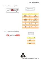
Страница 15: ...ctor HDMI Signal PIN PIN Signal HDMI_P2 1 2 GND HDMI_N2 3 4 HDMI_P1 GND 5 6 HDMI_N1 HDMI_P0 7 8 GND HDMI_N0 9 10 HDMI_CLKP GND 11 12 HDMI_CLKN NC 13 14 NC HDMI_CTRL_CLK 15 16 HDMI_CTRL_DAT GND 17 18 5V HPD 19 2 1 4 USB2 0 connector USB2 0 Signal PIN VCC 1 Data 2 Data 3 GND 4 ...

Отзывы: