background image

ESM-TGH 

User’s Manual 

82 ESM-TGH User

’s Manual


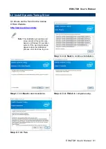
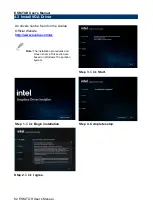
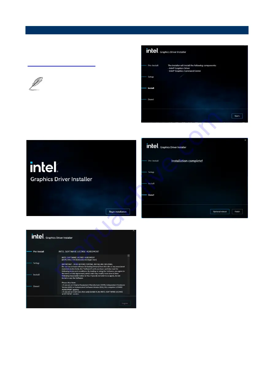
4.3 Install VGA Driver 


All drivers can be found on the Avalue 

Official Website: 

http://www.avalue.com.tw

. 


Note: 

The installation procedures and 

screen shots in this section are 
based on Windows 10 operation 
system.


Step 3.

 Click 

Start.


Step 1.

 Click 

Begin installation


Step 4.


Complete setup


Step 2.

 Click 

I agree


Содержание ESM-TGH

Страница 1: ...No E2047290200R ESM TGH 11th Gen Intel Core i7 i5 i3 Celeron BGA Processor Type 6 COMe Basic Module User s Manual 1st Ed 06 July 2022 Copyright Notice Copyright 2022 Avalue Technology Inc ALL RIGHTS RESERVED ...

Страница 2: ... USER WILL BE REQUIRED TO CORRECT THE INTERFERENCE AT HIS OWN EXPENSE Notice This guide is designed for experienced users to setup the system within the shortest time For detailed information please always refer to the electronic user s manual Copyright Notice Copyright 2022 Avalue Technology Inc ALL RIGHTS RESERVED No part of this document may be reproduced copied translated or transmitted in any...

Страница 3: ...sonably expected to cause the failure of the life support device or system or to affect its safety or effectiveness A Message to the Customer Avalue Customer Services Each and every Avalue s product is built to the most exacting specifications to ensure reliable performance in the harsh and demanding conditions typical of industrial environments Whether your new Avalue device is destined for the l...

Страница 4: ...1 CN1A 18 2 3 2 1 Signal Description COM Express Connector 1 CN1A 22 2 3 2 1 1 Audio Signals 22 2 3 2 1 2 Gigabit Ethernet Signals 22 2 3 2 1 3 PCI Express Signals 22 2 3 2 1 4 Flat Panel LVDS Signals 22 2 3 2 1 5 LPC eSPI Signals 23 2 3 2 1 6 GPIO Signals 23 2 3 2 1 7 Power System Management Signals 23 2 3 2 1 8 SATA Signals 24 2 3 2 1 9 USB Signals 24 2 3 2 1 10 I2C Signals 24 2 3 2 1 11 USB3 0 ...

Страница 5: ...PTT Configuration 42 3 6 2 4 Trusted Computing 42 3 6 2 5 APCI Settings 43 3 6 2 6 IT5571 Super IO Configuration 43 3 6 2 6 1 Serial Port 1 Configuration 44 3 6 2 6 2 Serial Port 2 Configuration 44 3 6 2 7 HW Monitor 45 3 6 2 7 1 Smart Fan Mode Configuration 46 3 6 2 8 S5 RTC Wake Settings 47 3 6 2 9 Serial Port Console Redirection 49 3 6 2 9 1 COM0 49 3 6 2 9 2 COM1 51 3 6 2 9 3 Console Redirecti...

Страница 6: ... 3 Board Panel Configuration 74 3 6 4 Security 76 3 6 5 Boot 77 3 6 6 Save and exit 78 3 6 6 1 Save Changes and Reset 78 3 6 6 2 Discard Changes and Reset 78 3 6 6 3 Restore Defaults 78 3 6 6 4 Launch EFI Shell from filesystem device 78 4 Drivers Installation 79 4 1 Install Chipset Driver 80 4 2 Install Dynamic Tuning Driver 81 4 3 Install VGA Driver 82 4 4 Install Ethernet Driver 83 4 5 Install M...

Страница 7: ... Caution Always ground yourself to remove any static charge before touching the CPU card Modern electronic devices are very sensitive to static electric charges As a safety precaution use a grounding wrist strap at all times Place all electronic components in a static dissipative surface or static shielded bag when they are not in the chassis 1 2 Packing List Before you begin installing your singl...

Страница 8: ...ESM TGH User s Manual 8 ESM TGH User s Manual 1 3 Document Amendment History Revision Date By Comment 1st July 2022 Avalue Initial Release ...

Страница 9: ...efully before attempting to set up ESM TGH series or change the standard configurations Whilst all the necessary information is available in this manual we would recommend that unless you are confident you contact your supplier for guidance Please be aware that it is possible to create configurations within the NVRAM that make booting impossible If this should happen clear the NVRAM settings see t...

Страница 10: ...70 solution I O Interface SOM PCI Express 1 PEGx16 Gen4 16 0 GT s support dGFX and NVMe Storage 8 PCIex1 Gen3 8 0 GT s UART 2 x UART 2 wire USB 2 0 8 x USB 2 0 USB 3 1 4 x USB3 2 Gen2x1 10 Gbps SATA 4 x SATA3 0 6 0Gb s DIO 8bit GPIO NCT5655Y WDG HW monitor FAN LPC 1 x LPC via eSPI to LPC bridge I2C Bus 1 x I2C SMBus 1 x SMBus Display Graphic Chipset Intel Iris Xe Gen 12 graphics Spec Resolution HD...

Страница 11: ... W Please consult product engineers for the production feasibility if the size is larger than 410x360mm or smaller than 80x70mm 125 95 mm 3 74 x 4 92 Weight 0 44lbs 0 2kg Vibration Test Random Vibration Operation 1 Test PSD 0 00454G Hz 1 5 Grms 2 System condition operation mode 3 Test frequency 5 500 Hz 4 Test axis X Y and Z axis 5 Test time 30 minutes per each axis 6 IEC60068 2 64 Test Fh 6 Stora...

Страница 12: ...is 6 operation mode 7 Reference IEC 60068 2 27 testing procedures Test Eb Shock Test Drop Test Package drop test Reference ISTA 2A Method IEC 60068 2 32 Test Ed Test Ea Drop Test 1 Test phase One corner three edges six faces 2 Test high 96 5cm 3 Package weight 5Kg 4 Test drawing OS Information Windows 10 IOT Enterprise Linux Yocto Android Support PS Carrier with EEV EX16 B1 version Note Specificat...

Страница 13: ...ESM TGH User s Manual ESM TGH User s Manual 13 1 6 Architecture Overview Block Diagram The following block diagram shows the architecture and main components of ESM TGH ...

Страница 14: ...ESM TGH User s Manual 14 ESM TGH User s Manual 2 Hardware Configuration ...

Страница 15: ...ESM TGH User s Manual ESM TGH User s Manual 15 2 1 Product Overview ...

Страница 16: ...nose pliers may be helpful when working with jumpers Connectors on the board are linked to external devices such as hard disk drives a keyboard or floppy drives In addition the board has a number of jumpers that allow you to configure your system to suit your application If you have any doubts about the best hardware configuration for your application contact your local distributor or sales repres...

Страница 17: ...tors 2 3 1 AT ATX mode selector SW1 Default AT ATX mode AT mode ATX mode 2 3 1 1 Signal Description AT ATX mode selection AT ATX mode Description AT mode Auto power on no need to press Power button to enable power on off ATX mode Press the power button to enable power on off ...

Страница 18: ...ND A100 B100 GND SER0_RX A99 B99 NC SER0_TX A98 B98 NC TYPE10 A97 B97 NC TPM_PP A96 B96 VGA_I2C_DAT NC A95 B95 VGA_I2C_CK NC A94 B94 VGA_VSYNC GPO0 A93 B93 VGA_HSYNC NC A92 B92 VGA_BLU 3 3V_SPI A91 B91 VGA_GRN GND A90 B90 GND PCIE_CLK_REF A89 B89 VGA_RED PCIE_CLK_REF A88 B88 NC CB_EDP_HDP A87 B87 ATX5VSB NC A86 B86 ATX5VSB GPI3 A85 B85 ATX5VSB LVDS_I2C_DAT EDP_AUX A84 B84 ATX5VSB LVDS_I2C_CK EDP_A...

Страница 19: ...B1 LVDS_A0 EDP_TX2 A72 B72 LVDS_B0 LVDS_A0 EDP_TX2 A71 B71 LVDS_B0 GND A70 B70 GND PCIE_TX0 A69 B69 PCIE_RX0 PCIE_TX0 A68 B68 PCIE_RX0 GPI2 A67 B67 WAKE1 GND A66 B66 WAKE0 PCIE_TX1 A65 B65 PCIE_RX1 PCIE_TX1 A64 B64 PCIE_RX1 GPI1 A63 B63 GPO3 PCIE_TX2 A62 B62 PCIE_RX2 PCIE_TX2 A61 B61 PCIE_RX2 GND A60 B60 GND PCIE_TX3 A59 B59 PCIE_RX3 PCIE_TX3 A58 B58 PCIE_RX3 GND A57 B57 GPO2 PCIE_TX4 A56 B56 PCIE...

Страница 20: ...A42 B42 USB3 GND A41 B41 GND USB4 A40 B40 USB5 USB4 A39 B39 USB5 USB_6_7_OC A38 B38 USB_4_5_OC USB6 A37 B37 USB7 USB6 A36 B36 USB7 THRMTRIP A35 B35 THRM NC A34 B34 I2C_DATA HDA_SDOUT A33 B33 I2C_CLK HDA_BITCLK A32 B32 SPKR GND A31 B31 GND HDA_RST A30 B30 HDA_SDIN0 HDA_SYNC A29 B29 HDA_SDIN1 S ATA_ACT A28 B28 NC BATLOW A27 B27 WDT SATA2_RX A26 B26 SATA3_RX SATA2_RX A25 B25 SATA3_RX SUS_S5 A24 B24 P...

Страница 21: ...BE0_CTREF A14 B14 SMB_SDA_S5 GBE0_MDI0 A13 B13 SMB_SCL_S5 GBE0_MDI0 A12 B12 PWRBTN GND A11 B11 GND GBE0_MDI1 A10 B10 LPC_CLK ESPI_CK GBE0_MDI1 A9 B9 LPC_DRQ1 ESPI_ALERT1 GBE0_LINK A8 B8 LPC_DRQ0 ESPI_ALERT0 GBE0_MDI2 A7 B7 LPC_AD3 ESPI_IO_3 GBE0_MDI2 A6 B6 LPC_AD2 ESPI_IO_2 GBE0_LINK2500 A5 B5 LPC_AD1 ESPI_IO_1 GBE0_LINK1000 A4 B4 LPC_AD0 ESPI_IO_0 GBE0_MDI3 A3 B3 LPC_FRAME ESPI_CS0 GBE0_MDI3 A2 B...

Страница 22: ...2 B1_DC X X MDI 3 B1_DD X X GBE0_ACT Gigabit Ethernet Controller 0 activity indicator active low GBE0_LINK Gigabit Ethernet Controller 0 link indicator active low GBE0_LINK100_1000 Gigabit Ethernet Controller 100 1000 Mbit sec link indicator active low GBE0_LINK2500 Gigabit Ethernet Controller 2500 Mbit sec link indicator active low 2 3 2 1 3 PCI Express Signals Signal Signal Description PCIE_TX 0...

Страница 23: ...g for all the serial input and output operations LPC_SERIRQ ESPI_CS1 LPC serial interrupt ESPI Mode eSPI Master Chip Select Outputs Driving Chip Select A low selects a particular eSPI slave for the transaction Each of the eSPI slaves is connected to a dedicated Chip Selectn pin LPC_DRQ0 ESPI_ALERT0 LPC serial DMA request ESPI Mode eSPI pins used by eSPI slave to request service from the eSPI maste...

Страница 24: ...transmit differential pair SATA 0 3 _RX Serial ATA Channel 0 3 receive differential pair ATA_ACT ATA parallel and serial activity indicator active low 2 3 2 1 9 USB Signals Signal Signal Description USB 0 7 USB differential pairs channels 0 through 7 USB_0_1_OC USB over current sense USB channels 0 and 1 USB_2_3_OC USB over current sense USB channels 2 and 3 USB_4_5_OC USB over current sense USB c...

Страница 25: ...EG_TX15 PEG_RX15 C101 D101 PEG_TX15 GND C100 D100 GND PEG_RX14 C99 D99 PEG_TX14 PEG_RX14 C98 D98 PEG_TX14 NC C97 D97 NC GND C96 D96 GND PEG_RX13 C95 D95 PEG_TX13 PEG_RX13 C94 D94 PEG_TX13 GND C93 D93 GND PEG_RX12 C92 D92 PEG_TX12 PEG_RX12 C91 D91 PEG_TX12 GND C90 D90 GND PEG_RX11 C89 D89 PEG_TX11 PEG_RX11 C88 D88 PEG_TX11 GND C87 D87 GND PEG_RX10 C86 D86 PEG_TX10 PEG_RX10 C85 D85 PEG_TX10 GND C84 ...

Страница 26: ..._RX6 C71 D71 PEG_TX6 GND C70 D70 GND PEG_RX5 C69 D69 PEG_TX5 PEG_RX5 C68 D68 PEG_TX5 RAPID_SHUTDOWN C67 D67 GND PEG_RX4 C66 D66 PEG_TX4 PEG_RX4 C65 D65 PEG_TX4 NC C64 D64 NC NC C63 D63 NC PEG_RX3 C62 D62 PEG_TX3 PEG_RX3 C61 D61 PEG_TX3 GND C60 D60 GND PEG_RX2 C59 D59 PEG_TX2 PEG_RX2 C58 D58 PEG_TX2 TYPE1 C57 D57 TYPE2 PEG_RX1 C56 D56 PEG_TX1 PEG_RX1 C55 D55 PEG_TX1 TYPE0 C54 D54 PEG_LAN_RV PEG_RX0...

Страница 27: ...GND DDI3_PAIR0 C40 D40 DDI2_PAIR0 DDI3_PAIR0 C39 D39 DDI2_PAIR0 DDI3_DDC_AUX_SEL C38 D38 NC DDI3_CTRLDATA_AUX C37 D37 DDI1_PAIR3 DDI3_CTRLCLK_AUX C36 D36 DDI1_PAIR3 NC C35 D35 NC DDI2_DDC_AUX_SEL C34 D34 DDI1_DDC_AUX_SEL DDI2_CTRLDATA_AUX C33 D33 DDI1_PAIR2 DDI2_CTRLCLK_AUX C32 D32 DDI1_PAIR2 GND C31 D31 GND NC C30 D30 DDI1_PAIR1 NC C29 D29 DDI1_PAIR1 NC C28 D28 NC RSVD7 C27 D27 DDI1_PAIR0 NC C26 ...

Страница 28: ...NC NC C16 D16 DDI1_CTRLDATA_AUX NC C15 D15 DDI1_CTRLCLK_AUX GND C14 D14 GND USB_SSRX3 C13 D13 USB_SSTX3 USB_SSRX3 C12 D12 USB_SSTX3 GND C11 D11 GND USB_SSRX2 C10 D10 USB_SSTX2 USB_SSRX2 C9 D9 USB_SSTX2 GND C8 D8 GND USB_SSRX1 C7 D7 USB_SSTX1 USB_SSRX1 C6 D6 USB_SSTX1 GND C5 D5 GND USB_SSRX0 C4 D4 USB_SSTX0 USB_SSRX0 C3 D3 USB_SSTX0 GND C2 D2 GND GND C1 D1 GND ...

Страница 29: ... floating the AUX pair is used for the DP AUX signals If pulled high the AUX pair contains the CRTLCLK and CTRLDATA signals DDI 1 3 _CTRLCLK_AUX DP AUX function if DDI 1 3 _DDC_AUX_SEL is no connect HDMI DVI 12C CTRLCLK if DDI 1 3 _DDC_AUX_SEL is pulled high DDI 1 3 _CTRLDATA_AUX DP AUX function if DDI 1 3 _DDC_AUX_SEL is no connect HDMI DVI 12C CTRLDATA if DDI 1 3 _DDC_AUX_SEL is pulled high DDI ...

Страница 30: ...User s Manual 2 4 Installing Heatsink Cooler Standard Temperature Heat spreader Cooler Step1 Using 5 screws M2 5 16L to lock the heat spreader and Cooler through PCB screw holes from top to bottom Note Screw Size Q TY M2 5 16L Ni 5pcs ...

Страница 31: ...Manual ESM TGH User s Manual 31 Wide Temperature Heat spreader Cooler Step1 Using 5 screws M2 5 16L to lock the heat spreader and Cooler through PCB screw holes from top to bottom Note Screw Size Q TY M2 5 16L Ni 5pcs ...

Страница 32: ...ESM TGH User s Manual 32 ESM TGH User s Manual 3 BIOS Setup ...

Страница 33: ...ishes the BIOS will seek an operating system on one of the disks and then launch and turn control over to the operating system While the BIOS is in control the Setup program can be activated in one of two ways By pressing F2 or Del immediately after switching the system on or By pressing the F2 or Del key when the following message appears briefly at the left top of the screen during the POST Powe...

Страница 34: ...u Quit and not save changes into NVRAM Status Page Setup Menu and Option Page Setup Menu Exit current page and return to Main Menu key Increase the numeric value or make changes key Decrease the numeric value or make changes F1 key General help only for Status Page Setup Menu and Option Page Setup Menu F2 key Previous Values F3 key Optimized defaults F4 key Save Exit Setup Navigating Through The M...

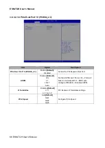
Страница 35: ...that your computer no longer is able to boot the BIOS supports an override to the NVRAM settings which resets your system to its defaults The best advice is to only alter settings which you thoroughly understand To this end we strongly recommend that you avoid making any changes to the chipset defaults These defaults have been carefully chosen by both your systems manufacturer to provide the absol...

Страница 36: ...appear on the screen The Main Menu allows you to select from several setup functions and exit choices Use the arrow keys to select among the items and press Enter to accept and enter the sub menu 3 6 1 Main Menu This section allows you to record some basic hardware configurations in your computer and set the system clock ...

Страница 37: ...em date Manually enter the day month and year 3 6 1 3 System Time Use the system time option to set the system time Manually enter the hours minutes and seconds Note The BIOS setup screens shown in this chapter are for reference purposes only and may not exactly match what you see on your screen Visit the Avalue website www avalue com tw to download the latest product and BIOS information ...

Страница 38: ...or basic operation through the following sub menus 3 6 2 1 CPU Configuration Use the CPU configuration menu to view detailed CPU specification and configure the CPU Item Options Description Intel VMX Virtualization Technology Disabled Enabled Default When enabled a VMM can utilize the additional hardware capabilities provided by Vanderpool ...

Страница 39: ... s Manual ESM TGH User s Manual 39 Technology Active Processor Cores All Default 1 2 3 4 5 6 7 8 Number of cores to enable in each processor package 3 6 2 2 Power Performance 3 6 2 2 1 CPU Power Management Control ...

Страница 40: ...allow for hardware controlled P states Turbo Mode Enabled Default Disabled Enable Disable processor Turbo Mode requires Intel Speed Step or Intel Speed Shift to be available and enabled 3 6 2 2 2 GT Power Management Control Item Option Description RC6 Render Standby Enabled Default Disabled Check to enable render standby support Maximum GT frequency Default Max Frequency Default 100Mhz 150Mhz 200M...

Страница 41: ... Manual ESM TGH User s Manual 41 3 6 2 3 PCH FW Configuration 3 6 2 3 1 Firmware Update Configuration Item Option Description ME FW Image Re Flash Disabled Default Enabled Enable Disable Me FW Image Re Flash function ...

Страница 42: ...TT Configuration 3 6 2 4 Trusted Computing Item Options Description Security Device Support Disable Enable Default Enables or Disables BIOS support for security device O S will not show Security Device TCG EFI protocol and INT1A interface will not be available ...

Страница 43: ...eep State This option may not be effective with some OS ACPI Sleep State Suspend Disabled S3 Suspend to RAM Default Select the highest ACPI sleep state the system will enter when the SUSPEND button is pressed 3 6 2 6 IT5571 Super IO Configuration You can use this item to set up or change the IT5571 Super IO configuration for serial ports Please refer to 3 6 2 6 1 3 6 2 6 2 for more information ...

Страница 44: ...figuration Set Parameters of Serial Port 1 COMA Serial Port 2 Configuration Set Parameters of Serial Port 2 COMB 3 6 2 6 1 Serial Port 1 Configuration Item Option Description Serial Port Enabled Default Disabled Enable or Disable Serial Port COM 3 6 2 6 2 Serial Port 2 Configuration ...

Страница 45: ... User s Manual 45 Item Option Description Serial Port Enabled Default Disabled Enable or Disable Serial Port COM 3 6 2 7 HW Monitor Item Options Description Smart Fan Function Enabled Disabled Default Enables or Disables Smart Fan ...

Страница 46: ...bles Smart Fan 3 6 2 7 1 Smart Fan Mode Configuration Item Option Description CPU Smart Fan Mode Manual Mode Default Mode 01 Mode 02 Mode 03 Mode 04 Mode 05 Mode 06 Mode 07 Mode 08 Mode 09 Mode 10 Mode 11 Mode 12 Mode 13 Mode 14 Mode 15 Mode 16 Mode 17 Mode 18 Mode 19 Mode 20 CPU Smart Fan Mode Select Fan PWM 0 255 255 Fan PWM duty ...

Страница 47: ...ake on alarm event Select Fixed Time system will wake on the hr min sec specified Select Dynamic Time System will wake on the current time Increase minute s Item Options Description Wake system from S5 Disabled Fixed Time Default Dynamic Time Enable or disable System wake on alarm event Select Fixed Time system will wake on the hr min sec specified Select Dynamic Time System will wake on ...

Страница 48: ...u would like the system to wake up Wake up hour 0 23 Select 0 23 For example enter 3 for 3am and 15 for 3pm Wake up minute 0 59 Select 0 59 For Minute Wake up second 0 59 Select 0 59 For Second Item Options Description Wake system from S5 Disabled Fixed Time Dynamic Time Default Enable or disable System wake on alarm event Select Fixed Time system will wake on the hr min sec specified Select Dynam...

Страница 49: ...3 6 2 9 Serial Port Console Redirection Item Options Description Console Redirection Disabled Default Enabled Console Redirection Enable or Disable Console Redirection EMS Disabled Default Enabled Console Redirection Enable or Disable 3 6 2 9 1 COM0 ...

Страница 50: ... allow for error detection They can be used as an additional data bit Stop Bits 1 Default 2 Stop bits indicate the end of a serial data packet A start bit indicates the beginning The standard setting is 1 stop bit Communication with slow devices may require more than 1 stop bit Flow Control None Default Hardware RTS CTS Flow control can prevent data loss from buffer overflow When sending data if t...

Страница 51: ... lines may require lower speeds Data Bits 7 8 Default Data Bits Parity None Default Even Odd Mark Space A parity bit can be sent with the data bits to detect some transmission errors Even parity bit is 0 if the num of 1 s in the data bits is even Odd parity bit is 0 if num of 1 s in the data bits is odd Mark parity bit is always 1 Space Parity bit is always 0 Mark and Space Parity do not allow for...

Страница 52: ...ith this mode enabled only text will be sent This is to capture Terminal data Resolution 100x31 Disabled Default Enabled Enables or disables extended terminal resolution Putty KeyPad VT100 Default Intel Linux XTERMR6 SCO ESCN VT400 Select FunctionKey and KeyPad on Putty 3 6 2 9 3 Console Redirection Settings Item Option Description Out of Band Mgmt Port COM0 Default Microsoft Windows Emergency Man...

Страница 53: ...equire lower speeds Flow Control None Default Hardware RTS CTS Software Xon Xoff Flow control can prevent data loss from buffer overflow When sending data if the receiving buffers are full a stop signal can be sent to stop the data flow Once the buffers are empty a start signal can be sent to re start the flow Hardware flow control uses two wires to send start stop signals 3 6 2 10 Acoustic Manage...

Страница 54: ...ec USB mass storage device Start Unit command time out Device power up delay Auto Default Manual Maximum time the device will take before it properly reports itself to the Host Controller Auto uses default value for a Root port it is 100ms for a Hub port the delay is taken form Hub descriptor Mass Storage Devices Auto Default Floppy Forced FDD Hard Disk CD ROM Mass storage device emulation type AU...

Страница 55: ...iguration Item Options Description Network Stack Enabled Disabled Default Enable Disable UEFI Network Stack Item Options Description Network Stack Enabled Default Disabled Enable Disable UEFI Network Stack Ipv4 PXE Support Enabled Enable Ipv4 PXE Boot Support If disabled IPV4 ...

Страница 56: ...ated Ipv6 PXE Support Enabled Disabled Default Enable Ipv6 PXE Boot Support If disabled IPV6 PXE boot option will not be created Ipv6 HTTP Support Enabled Disabled Default Enable Ipv6 HTTP Boot Support If disabled IPV4 HTTP boot option will not be created PXE boot wait time 0 Wait time to press ESC key to abort the PXE boot Media detect count 1 Number of times presence of media will be checked 3 6...

Страница 57: ...H User s Manual ESM TGH User s Manual 57 3 6 2 14 Tls Auth Configuration 3 6 2 14 1 Console Redirection Settings Item Description Cert GUID Input digit character in 11111111 2222 3333 4444 1234567890ab format ...

Страница 58: ...ESM TGH User s Manual 58 ESM TGH User s Manual 3 6 3 Chipset 3 6 3 1 System Agent SA Configuration Item Option Description VT d Enabled Default Disabled VT d capability ...

Страница 59: ...ed Enable Disable DDR Ecc Support Note Only effected on specify SKU Max TOLUD Dynamic Default 1 GB 1 25 GB 1 5 GB 1 75 GB 2 GB 2 25 GB 2 5 GB 2 75 GB 3 GB 3 25 GB 3 5 GB Maximum Value of TOLUD Dynamic assignment would adjust TOLUD automatically based on largest MMIO length of installed graphic controller 3 6 3 1 2 Graphics Configuration ...

Страница 60: ...t the Aperture Size Note Above 4GB MMIO BIOS assignment is automatically enabled when selecting 2048MB aperture To use this feature please disable CSM Support VBT Select eDP MIPI 3 HDMI VGA 3 DP VGA Default Select VBT for GOP Driver 3 HDMI VGA Port D E F are HDMI only 3 DP _VGA Port D E F are DP 3 6 3 2 PCH IO Configuration Item Option Description State After G3 S0 State Default S5 State Specify w...

Страница 61: ...ess Configuration 3 6 3 2 1 1 PCIe Root Port 5 PCIEX4_1 1 Item Option Description PCIe Root Port 5 PCIEX4_1 1 Enabled Default Disabled Control the PCI Express Root Port ASPM Disabled Default L0s Set the ASPM Level Force L0s Force all links to L0s State AUTO BIOS auto ...

Страница 62: ...3 6 3 2 1 2 PCIe Root Port 6 PCIEX4_1 2 Item Option Description PCIe Root Port 6 PCIEX4_1 2 Enabled Default Disabled Control the PCI Express Root Port ASPM Disabled Default L0s L1 L0sL1 Auto Set the ASPM Level Force L0s Force all links to L0s State AUTO BIOS auto configure DISABLE Disables ASPM L1 Substates Disabled Default L1 1 L1 1 L1 2 PCI Express L1 Substates settings PCIe Speed Auto Default G...

Страница 63: ...nabled Default Disabled Control the PCI Express Root Port ASPM Disabled Default L0s L1 L0sL1 Auto Set the ASPM Level Force L0s Force all links to L0s State AUTO BIOS auto configure DISABLE Disables ASPM L1 Substates Disabled Default L1 1 L1 1 L1 2 PCI Express L1 Substates settings PCIe Speed Auto Default Gen1 Gen2 Gen3 Configure PCIe Speed ...

Страница 64: ...nabled Default Disabled Control the PCI Express Root Port ASPM Disabled Default L0s L1 L0sL1 Auto Set the ASPM Level Force L0s Force all links to L0s State AUTO BIOS auto configure DISABLE Disables ASPM L1 Substates Disabled Default L1 1 L1 1 L1 2 PCI Express L1 Substates settings PCIe Speed Auto Default Gen1 Gen2 Gen3 Configure PCIe Speed ...

Страница 65: ... Default Disabled Control the PCI Express Root Port ASPM Disabled Default L0s L1 L0sL1 Auto Set the ASPM Level Force L0s Force all links to L0s State AUTO BIOS auto configure DISABLE Disables ASPM L1 Substates Disabled Default L1 1 L1 1 L1 2 PCI Express L1 Substates settings PCIe Speed Auto Gen1 Gen2 Gen3 Default Configure PCIe Speed ...

Страница 66: ...Enabled Default Disabled Control the PCI Express Root Port ASPM Disabled Default L0s L1 L0sL1 Auto Set the ASPM Level Force L0s Force all links to L0s State AUTO BIOS auto configure DISABLE Disables ASPM L1 Substates Disabled Default L1 1 L1 1 L1 2 PCI Express L1 Substates settings PCIe Speed Auto Default Gen1 Gen2 Gen3 Configure PCIe Speed ...

Страница 67: ...Enabled Default Disabled Control the PCI Express Root Port ASPM Disabled Default L0s L1 L0sL1 Auto Set the ASPM Level Force L0s Force all links to L0s State AUTO BIOS auto configure DISABLE Disables ASPM L1 Substates Disabled Default L1 1 L1 1 L1 2 PCI Express L1 Substates settings PCIe Speed Auto Default Gen1 Gen2 Gen3 Configure PCIe Speed ...

Страница 68: ...Enabled Default Disabled Control the PCI Express Root Port ASPM Disabled Default L0s L1 L0sL1 Auto Set the ASPM Level Force L0s Force all links to L0s State AUTO BIOS auto configure DISABLE Disables ASPM L1 Substates Disabled Default L1 1 L1 1 L1 2 PCI Express L1 Substates settings PCIe Speed Auto Default Gen1 Gen2 Gen3 Configure PCIe Speed ...

Страница 69: ...Enabled Default Disabled Control the PCI Express Root Port ASPM Disabled Default L0s L1 L0sL1 Auto Set the ASPM Level Force L0s Force all links to L0s State AUTO BIOS auto configure DISABLE Disables ASPM L1 Substates Disabled Default L1 1 L1 1 L1 2 PCI Express L1 Substates settings PCIe Speed Auto Default Gen1 Gen2 Gen3 Configure PCIe Speed ...

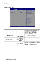
Страница 70: ...for Clock0 Platform POR Disabled Default Platform POR CLKREQ signal is assigned to CLKSRC according to board layout Disabled CLKREQ will not be used Clock4 assignment Platform POR Enabled Default Disabled Platform POR clock is assigned to PCIe port or LAN according to board layout Enabled keep clock enabledeven if unused Disabled Disable clock ClkReq for Clock4 Platform POR Disabled Default Platfo...

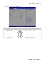
Страница 71: ...iguration Item Options Description SATA Controller s Enabled Default Disabled Enable Disable SATA Device SATA Speed Limitation AUTO Default Gen1 1 5 Gb s Gen2 3 0 Gb s Gen3 6 0 Gb s Set the maximum speed of SATA SATA1 2 3 4 Enabled Default Disabled Enable or Disable SATA Port ...

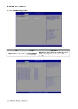
Страница 72: ...GH User s Manual 3 6 3 2 3USB Configuration Item Option Description USB Port Disable Override Disabled Default Select Per Pin Selectively Enable Disable the corresponding USB port from reporting a Device Connection to the controller ...

Страница 73: ...nable Disable this USB Physical Connector physical port Once disabled any USB devices plug into the connector will not be detected by BIOS or OS 3 6 3 2 4HD Audio Configuration Item Option Description HD Audio Disabled Enabled Default Control Detection of the HD Audio device Disable HDA will be unconditionally disabled Enabled HDA will be unconditionally enabled Audio DSP Disabled Enabled Default ...

Страница 74: ...00 18 1 1280x800 18 1 1920x1200 24 2 1920x1080 18 2 1280x1024 24 2 1440x900 18 2 1600x1200 24 2 1366x768 24 1 1920x1080 24 2 1680x1050 24 2 Port1 EDP to LVDS Chrotel 7511 Panel EDID Option Panel Brightness Control Method BIOS Default OS Driver Panel Brightness Control Method 1 BIOS 2 Brightness Button 3 Variable Resistor 4 OS Driver Panel Brightness 00 25 50 75 100 Default Select Panel back light ...

Страница 75: ...sec 50 sec 1 min 2 min 10 min 30 min Select WatchDog eSPI decode Port 80h via CS0 Default via CS1 via CS2 via CS3 Decode range 80h 84h 86h 88h 8Ch 8eh 90h 94h 96h 98h 9Ch 9Eh eSPI decode Port 4Eh 4Fh via CS0 Default via CS1 via CS2 via CS3 Set CS IO rounting for 4Eh Decode range 4Eh 4Fh eSPI decode Port 2Eh 2Fh via CS0 Default via CS1 via CS2 via CS3 Set CS IO rounting for 2Eh Decode range 2Eh 2Fh...

Страница 76: ...ESM TGH User s Manual 76 ESM TGH User s Manual 3 6 4 Security Administrator Password Set setup Administrator Password User Password Set User Password ...

Страница 77: ...mpt Timeout 1 65535 Number of seconds to wait for setup activation key 65535 0xFFFF means indefinite waiting Bootup NumLock State On Off Default Select the keyboard NumLock state Quiet Boot Disabled Enabled Default Enables or disables Quiet Boot option Boot Option 1 Set the system boot order ...

Страница 78: ... setup program are discarded The setup program then exits and reboots the controller 3 6 6 3 Restore Defaults This option restores all BIOS settings to the factory default This option is useful if the controller exhibits unpredictable behavior due to an incorrect or inappropriate BIOS setting 3 6 6 4 Launch EFI Shell from filesystem device Attempts to Launch EFI Shell application Shellx64 efi from...

Страница 79: ...TGH User s Manual ESM TGH User s Manual 79 4 Drivers Installation Note Installation procedures and screen shots in this section are for your reference and may not be exactly the same as shown on your screen ...

Страница 80: ... Official Website http www avalue com tw Note The installation procedures and screen shots in this section are based on Windows 10 operation system If the warning message appears while the installation process click Continue to go on Step 3 Click Install Step1 Click Next Step 4 Complete setup Step 2 Click Accept ...

Страница 81: ...w avalue com tw Note The installation procedures and screen shots in this section are based on Windows 10 operation system If the warning message appears while the installation process click Continue to go on Step 3 Click Next to continue installation Step1 Click Next to start installation Step 4 Click Finish to complete setup Step 2 Click Yes ...

Страница 82: ...drivers can be found on the Avalue Official Website http www avalue com tw Note The installation procedures and screen shots in this section are based on Windows 10 operation system Step 3 Click Start Step 1 Click Begin installation Step 4 Complete setup Step 2 Click I agree ...

Страница 83: ...nd on the Avalue Official Website http www avalue com tw Note The installation procedures and screen shots in this section are based on Windows 10 operation system Step 3 Click Next to continue setup Step 1 Click Install Drivers and Software Step 4 Click Next Step 2 Click Next Step 5 Click Install ...

Страница 84: ...ESM TGH User s Manual 84 ESM TGH User s Manual Step 6 Click Finish to complete the setup ...

Страница 85: ...ue com tw Note The installation procedures and screen shots in this section are based on Windows 10 operation system If the warning message appears while the installation process click Continue to go on Step 3 Click Next to continue installation Step1 Click Next to start installation Step 4 Click Finish to complete setup Step 2 Click Next ...

Страница 86: ...ww avalue com tw Note The installation procedures and screen shots in this section are based on Windows 10 operation system If the warning message appears while the installation process click Continue to go on Step 3 Click Next Step1 Click Next to start installation Step 4 Click Next Step 2 Click Next Step 5 Click Finish to complete setup ...

Страница 87: ...ESM TGH User s Manual ESM TGH User s Manual 87 5 Mechanical Drawing ...

Страница 88: ...ESM TGH User s Manual 88 ESM TGH User s Manual Unit mm ...

Отзывы: