background image

AVDT-BOB 

User’s manual

 v1.6 


Page 20 / 25 


4.6.4


GPIO menu (available for AVDT-BOB-ADE8io/ADX8io 

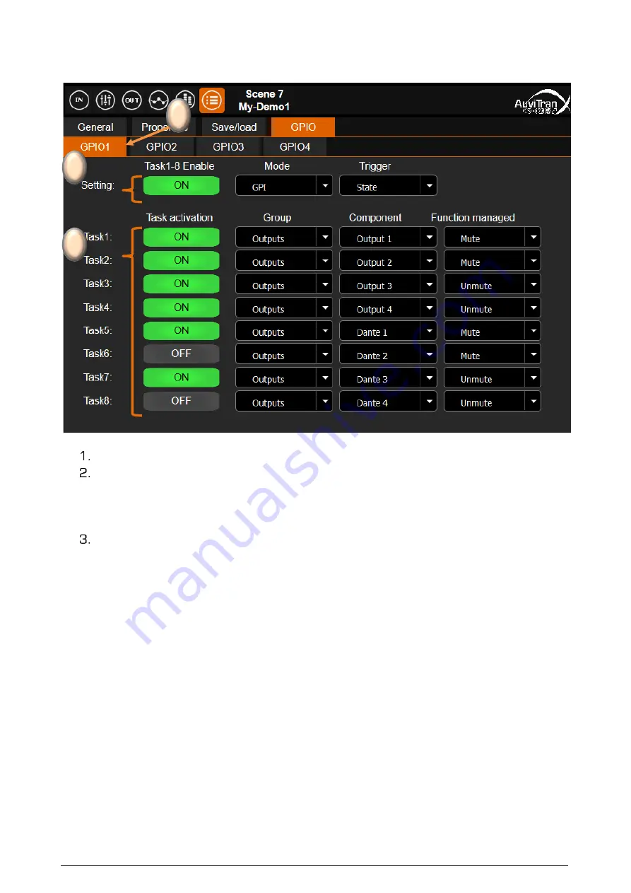
The GPIO interface allows to specify the mode and actions associated to the 4x GPIO. 


[

GPIO tabs

] allow to select the GPIO. The selection is done just by clicking on it.  


[

Setting fields

] enable for the selected GPIO: 

1.


To activate/stop the 

GPIO trigger 

and all enabled tasks for that GPIO 

2.


To select one of the 

GPIO Mode

GPI

GPO

 or 

Fader


3.


To choose a 

Trigger


Condition

: “

Pulse

 or 

State

 (for the GPI mode only) 


 [

Task fields

] allows to define up to 8 independent actions associated to that GPIO: 

1.


To activate/stop the associated task 

2.


To select the “

Group


of components: “

Inputs

”, “

Mixers

” or “

Outputs


3.


To select the “

Component

” to control which depends of the group selected


4.


To choose the 

Trigger

 type when available (depend of the component 

selected) 

 
Notices: 

-


The management of the GPIOs is running only when a GPIO refresh rate is set (cf. 

chapter “General software setting menu”)


-


When a GPIO is set to ON, it is analyzed at 3 different frequencies defined by 
GPIO refresh rate (i.e. Fast, Medium, Low) 

-


The task(s) associated to GPIO depend of selected 

GPIO Mode


1


2


3


Содержание AVDT-BOB

Страница 1: ...AVDT BOB User s manual v1 6 Page 1 25 AVDT BOB User s manual www auvitran com AVDT BOB AE4io AVDT BOB AE8io AVDT BOB AS8io AVDT BOB ADE8io AVDT BOB AEG6io AVDT BOB ADX8io Rear AVDT BOB ADX8io Front ...

Страница 2: ...g block 10 3 5 Mixing Processing block 11 3 6 Output processing block 11 4 AVDT BOB User s Interface 12 4 1 Bar menu for interface selection 12 4 2 Inputs interface 12 4 3 Mixers interface 13 4 4 Outputs interface 14 4 5 Processing interface 15 4 5 1 EQ Processing view 16 4 5 2 Limiter Compressor view 17 4 6 Parameter interface 17 4 6 1 General software setting menu 18 4 6 2 Network parameters men...

Страница 3: ...re bound to change and be upgraded without notice Please read carefully the User s manual as the new functionalities will be described therein 1 2 TRADEMARKS All trademarks listed in this manual are the exclusive property of their respective owners They are respected as is by AuviTran Any use of these trademarks must receive prior approval of their respective owners For any question please contact...

Страница 4: ...C IP router the Link LED of the connected port will be On and the Act LED will start flashing AVDT BOB can be daisy chained to other Dante device via the remaining port s thanks to an internal gigabit switch that connects Physical Ethernet ports Main Aux Dante component User Interface of ARM processor managing Web 2 0 DSP and Mic preamps AVDT BOB has 2x independent IP network addresses and 2 assoc...

Страница 5: ...y other information Notices Using the Dante controller it is possible to run commands by setting specific Dante names in an AVDT BOB all command name must be filled with the maximum of x at end Setting AVTxCMD GIPxxxxxxxxxxxxxxxxxxxx as Dante Name in an AVDT BOB will request to get back the IP address of the AVDT user Interface In reply the Dante Name of the module will be changed back to AVTxANS ...

Страница 6: ...ante information on the AVDT BOB Select the AVDT BOB in the left list called Network controller and Control Tab in the right windows as describe bellow See chapter 3 for interface description Notices If your device doesn t appear your network configuration is probably not good 1 Go to the AVS Control Panel using Edit Control panel menu or press Ctrl P 2 Select a valid network adapter in the Dante ...

Страница 7: ...ame see 2 2 terminated by local in Web Browser address field bar to ask it accessing to the IP server with a local name in your local area network local at the end is needed to force mDNS local name in the browser AVDT BOB 145 UI local for instance to connect to AVDT BOB serial number 145 if the Dante name was not changed The Browser will display AuviTran s Logo during the loading of the user s in...

Страница 8: ...to Dante from their Main or Aux gigabits Ethernet ports These input output signals are named as follows in these AVDT BOB Mic Line1 2 for the signals coming from Mic Line inputs AES EBU ch1 2 for the signals coming from AES EBU input Dante In1 4 for the signals coming from Dante network Line Out1 2 for the signals sending to Line outputs AES EBU ch1 2 for the signals sending to AES EBU output Dant...

Страница 9: ...g Dante Inputs Dante_In1 4 Mixing Master1 4 Direct Out Mic Line1 2 Processed Mic Line1 2 Processed Dante1 4 AVDT BOB AE4io s schematic AVDT BOB AE8io AS8io s schematic Analog Inputs MicLine1 4 Input Processing Output Processing Analog Outputs Line_Out1 4 Dante Outputs Dante_Out1 4 Mixing Processing Mixing Master1 4 Direct Out Mic Line1 2 Processed Mic Line1 2 Mic Line Digital Input 1 4 Input Proce...

Страница 10: ...ne1 4 2 G G 48V Mic Preamp fader Dante In1 4 Dante fader 4 4 2 φ φ On Off On Off DirectOut 1 4 2 Processed input1 4 2 Processed Dante1 4 Meter Meter Input Processing EQ Dyn Processing on Dante 48V Diagram of the AVDT BOB s Input Processing block for AE4io AE8io AEG6io AS8io versions Mic Line1 2 G G 48V Mic Preamp fader Dante In1 2 Dante fader 4 2 φ φ On Off On Off DirectOut 1 2 Processed input1 2 ...

Страница 11: ...Dante1 4 Processed Input1 4 2 DirectOut1 4 2 Meter 1ch source Select 4 2 4 2 4 2 4 2 4 4 Mixing Master 4 4 4 4 4 Line Out fader Output Processing EQ Dyn Processed Input1 4 2 DirectOut1 4 2 Meter 4 2 4 2 4 2 4 2 4 4 Mixing Master 4 4 4 4 4 Dante Out fader 1ch source Select Analog Digital Ouput1 4 DA G G 4 4 On Off On Off On Off On Off 4 2 4 2 Dante Out1 4 Line Out1 4 2 Diagram of the AVDT BOB s Out...

Страница 12: ...es of faders and buttons manage the Dante processing On the top of a slice the value of the gain preamp or digital reflects the fader position On 2nd line miniatures of EQ or DYN indicates the processing position Mic Dante On 3rd line On Off Phi buttons control the activation or phase inversion On 4th line 48V buttons control the phantom power of the input Mic Line On bottom a reminder of the sour...

Страница 13: ...played On last line colored label buttons enable the user to customize the input slice labels Notices Faders control individually the input mixing gains Each input of a mixer can be enabled On or muted Off Each mixer has a Master fader controlling the Master mixer output level Each master mixer output can be enabled On or mute Off Digital fader manages gain in the range Inf then 80dB to 12dB per s...

Страница 14: ...res of EQ or DYN show the processing done on analog outputs On 4th line On Off buttons control the activation or the mute of the output slices On bottom a reminder of the physical types and names of each slice are displayed On last line colored label buttons display user s name color of the slices They can be individually customized by a long click or a double click on a button 3 Selected input so...

Страница 15: ...namic windows limiter compressor On the top left a reminder indicates to which physical input User s name the EQ DYN processing is attached The slice on which the EQ DYN processing will be done is displayed highlight in orange On the bottom 12 10 colored user s names buttons enable to select the slice on which the EQ DYN processing will be modified This button line can be dragged left right to acc...

Страница 16: ...ted EQ band frequency and gain parameters and pinch under them control set their width Q parameter Right faders enable to modify smoothly the parameters of highlight HPF EQ button On Off button activates bypass the EQ processing without modifying the parameters HPF On Off button activate disable the high pass filter Reset button reset all EQ processing parameters Cancel button cancel all modificat...

Страница 17: ...old Release parameters Attack attack time in ms Hold sets the time the gate will remain open after the signal has fallen below the threshold Release return time in ms On Off button activates bypass the Limiter compressor processing without modifying the parameters Soft knee button activates disables the soft knee of the compression Reset button reset all limiter compressor processing parameters Ca...

Страница 18: ...ocessing 2 to Mic Line2 or to Dante in 2 Switch processing 3 defines the link of processing 3 to Mic Line3 or to Dante in 3 Switch processing 4 defines the link of processing 4 to Mic Line4 or to Dante in 4 Specified the slice link button mode Gain only or All components Gain buttons Deactivates or defines the GPIO refresh rate for AVDT BOB ADE8io ADX8io only 4 6 2 Network parameters menu This tab...

Страница 19: ...selection is done just by clicking on it The selected scene Slot is highlight in orange The Save button enables to set a name and to save the current settings for the selected highlight Scene slot The Load button enables to load in the AVDT BOB the saved settings for the selected highlight Scene slot On the top left just after the parameter icon a reminder of the last saved load scene is displayed...

Страница 20: ...State for the GPI mode only Task fields allows to define up to 8 independent actions associated to that GPIO 1 To activate stop the associated task 2 To select the Group of components Inputs Mixers or Outputs 3 To select the Component to control which depends of the group selected 4 To choose the Trigger type when available depend of the component selected Notices The management of the GPIOs is ru...

Страница 21: ...Off AES3 in1 2 Mute Unmute Phase On Off Dante in1 4 Mute Unmute Phase On Off All Inputs Mute Unmute Mixers Master1 4 Mute Unmute All Mixers Mute Unmute Outputs Analog out1 2 Mute Unmute AES3 out1 2 Mute Unmute Dante out1 4 Mute Unmute All Outputs Mute Unmute Scene SceneName1 7 Load Notices The actions are treated sequentially from task 1 to task 8 When State is selected for the GPI trigger all fun...

Страница 22: ...Mute Unmute Phase On Off Dante in1 4 Mute Unmute Phase On Off Mixers Master1 4 Mute Unmute Outputs Analog out1 2 Mute Unmute AES3 out1 2 Mute Unmute Dante out1 4 Mute Unmute Notices The automation is evaluated from GPIO1 to GPIO4 In GPO mode the Trigger function on a component determines the internal button in an AVDT BOB that will set reset the external GPIO For instance in the previous screen sh...

Страница 23: ...nputs MicLine1 2 Gain Reverse gain Dante in1 4 Gain Reverse gain All Inputs Gain Reverse gain Mixers Master1 4 Gain Reverse gain All Mixers Gain Reverse gain Outputs Analog out1 2 Gain Reverse gain AES3 out1 2 Gain Reverse gain Dante out1 4 Gain Reverse gain All Outputs Gain Reverse gain Notices The automation is evaluated from GPIO1 to GPIO4 The GPIO actions are treated sequentially from task 1 t...

Страница 24: ...se pins are located For the AVDT BOB ADE8io on the top left 6 pole Euroblock For the AVDT BOB ADX8io on the SUBD pins 5 1 GPIO Connection for GPI mode The GPIO can be configurable as a GPI via the software interface In this case the GPIO must be wired as displayed bellow Notes Each GPI is weakly pulled down to 100KΩ Input range is between 0 12V referenced to device ground Input a level 1 8V for a ...

Страница 25: ... 3 GPIO Connection for Fader mode The GPIO can be configurable as a Fader via the software interface In this case the GPIO must be wired as displayed bellow Notes Each Fader ADC is weakly pulled down to 100KΩ Each Fader ADC is linear to its input voltage in a range of is 0 to 10V referenced to device ground 0V referees to minimum value 10V referees to maximum value VCC provides a voltage between 1...

Отзывы: