background image

INSTALLATION

ASSEMBLE TOOLS AND ACCESSORIES:

PLAN YOUR SYSTEM LAYOUT:

IMPORTANT GUIDELINES:

PLACEMENT AND MOUNTING:

Wire Cutters/Crimpers/Strippers

Prior to installing your MX-1, be sure that you have identified a good mounting location that will allow for easy access
to make adjustments. Determine the best routes for your wires and lay them out before permanent installation.


In most applications, mounting the MX-1 module close to the amplifier is ideal. Once the mounting location is
determined, mark the 4 mounting holes with a marker. Prior to pre-drilling the holes, ensure that there are dangers
on the other side of the metal. Once the holes have been pre-drilled, clean the metal shavings from the area and
mount the MX-1 into location.  


Digital Multi-Meter

Supplied Screws

Supplied Allen Wrench

Small Flathead Screwdriver

Wrench For Battery Post

Drill With Phillips Bit

1/8” Diameter Heat Shrink Tubing

18 Gauge Power Wire(Application Appropriate Length)

18 Gauge Ground Wire(Application Appropriate Length)

18 Gauge Remote Wire(Application Appropriate Length)

- Read the entire manual prior to attempting the installation.
- Run all RCA’s so that they are far from any high current wires.
- Always inspect an area prior to drilling. Avoid cutting or drilling into electrical wires, fluid lines and gas tanks.
- All power wires connected to the front battery should have the appropriate fuse in line within 12” of the battery
  terminal.
- The ground connection integrity to the chassis is very important. The best way to achieve a good, solid electrical
  and mechanical contact is to use a large round crimp lug, crimped and soldered to the ground wire. Then scrape
  or sand the paint off of the vehicle chassis, slightly larger than the ground lug, at the connection point. Drill a
  clearance hole in the chassis, the same size as the lug hole, and use a bolt, spring washer and nut to securely
  fasten the ground lug. Use petroleum jelly to coat the bolt/lug connection to prevent oxidization with time.

SUBWOOFER

INPUT

LEVEL

40V

4V

SUBWOOFER

OUTPUT

LEVEL

1V

9V

LOW PASS

FILTER

24 dB/OCT

250Hz

35Hz

BOOST

PARAMETRIC BASS EQ

BANDWIDTH

FREQUENCY

+10 dB

100Hz

0dB

30Hz

SUBSONIC

FILTER

24 dB/OCT

35Hz

15Hz

MX-1

LINE LEVEL

CONVERTER

REAR HIGH 

PASS FILTER

12 dB/OCT

200Hz

15Hz

FRONT HIGH 

PASS FILTER

12 dB/OCT

200Hz

15Hz

FRONT & REAR

STEREO OUTPUT

LEVEL

4V

9V

40V

4V

HIGH LEVEL
F & R INPUT
 CONTROL

4 CH MONO / HIGH LEVEL

SUBWOOFER
INPUT MODE
 SELECTOR

GREEN: PRE-CLIP
YELLOW: SOFT CLIP
RED: HARD CLIP

CLIPPING CONTROL

2

Содержание Maxxsonics MX-1

Страница 1: ...MX SERIES MX 1 MX 2 MX 3 MX 4 OEM INTEGRATION ACCESSORIES...

Страница 2: ...rWire nofactoryamp 8 MX 2FeatureDescriptions 9 MX 2MainDiagram 10 MX 2ConnectingLowLevelRCACablestoAmplifier 11 MX 2ConnectingHighLevelSpeakerWires nofactoryamp 12 MX 3FeatureDescriptions 13 MX 3MainD...

Страница 3: ...m High to Low Level Converter Easily add an aftermarket amplifier to any OEM radio system with this deluxe line level controller that converts factory high level speaker wires into unbalanced low leve...

Страница 4: ...hat they are far from any high current wires Always inspect an area prior to drilling Avoid cutting or drilling into electrical wires fluid lines and gas tanks All power wires connected to the front b...

Страница 5: ...boosted with the PARAMETRIC BASS EQ feature LOW PASS FILTER Variable from 35Hz to 250Hz This filter features a 24dB per Octave roll off This means that the LOW PASS FILTER has a steep cut off and all...

Страница 6: ...he REAR HIGH PASS FILTER allows frequencies above your selected setting to pass thru while cutting out frequencies below your selected setting for the rear speakers FRONT REAR STEREO OUTPUT LEVEL Vari...

Страница 7: ...TPUT LEVEL 4V 9V 40V 4V HIGH LEVEL F R INPUT CONTROL 4 CH MONO HIGH LEVEL SUBWOOFER INPUT MODE SELECTOR GREEN PRE CLIP YELLOW SOFT CLIP RED HARD CLIP CLIPPING CONTROL SPEAKER WIRE INPUT R F L F R R L...

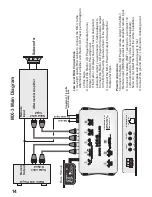
Страница 8: ...hite and Right red polarity as well as Front and Rear on both MX 1 and the aftermarket amplifier Power Connections 1 Connect the remote REM OUT output of the MX 1 to the remote input on the aftermarke...

Страница 9: ...ermarket amplifier as shown in the diagram on page 4 If you experience audible noise distortion in the speakers upon completion of the installation connect the MX 1 Radio ground to the factory radio g...

Страница 10: ...ions 1 Cut the factory radio speaker wires from the radio to the speakers in half 2 Connect the speaker wires from the radio side to the MX 1 color coded wires as shown in the diagram 3 Connect the ot...

Страница 11: ...ow your selected setting for the front speakers REAR HIGH PASS FILTER Variable from 15Hz to 200Hz This filter features a 12dB per Octave roll off This means that the REAR HIGH PASS FILTER has a gradua...

Страница 12: ...NT HIGH PASS FILTER 12 dB OCT 200Hz 15Hz REAR HIGH PASS FILTER 12 dB OCT 200Hz 15Hz 40V 4V HIGH LEVEL F R INPUT CONTROL FRONT REAR STEREO OUTPUT LEVEL 4V 9V R F L F R R L R RADIO SPEAKER WIRE INPUT Bl...

Страница 13: ...larity as well as Front and Rear on both MX 2 and the aftermarket amplifier Power Connections 1 Connect the remote REM OUT output of the MX 2 to the remote input on the aftermarket amplifier 2 Connect...

Страница 14: ...r code and polarity chart above 3 Connect the other end of the wires from the speakers to the aftermarket amplifier as shown in the diagram on page 4 If you experience audible noise distortion in the...

Страница 15: ...steep cut off and allows for very precise tuning The SUBSONIC FILTER allows frequencies above your setting to pass thru while cutting out damaging and unwanted frequencies below your selected setting...

Страница 16: ...igh quality RCA cables to connect the MX 3 to the aftermarket amplifier and Radio CD Player per the diagram on this page 2 Connect the Radio CD Player Subwoofer mono Output to the MX 3 Pre Amp Input I...

Страница 17: ...age to your amplifier Use caution when adjusting the signal output to be provided to your amplifier as you can damage your amplifier if you provide more signal than your amplifier is rated to handle S...

Страница 18: ...Green Factory Radio MX 4 ADD A SUB 40V 4V HIGH LEVEL LR RR INPUT CONTROL SUBWOOFER OUTPUT LEVEL 4V 9V REMOTE OUTPUT BATTERY w 5 amp fuse REMOTE INPUT CHASSIS SUB AMP OUTPUT R L Black Radio Ground Ora...

Страница 19: ......

Страница 20: ...ocalizetheproblem Noiseproblems Systemnoisecanbedividedintotwocategories hiss andelectricalinterference Hiss orwhitenoise 1 Highlevelsofwhitenoiseusuallyoccurwhenlevelcontrolsareturneduptoohigh readju...

Страница 21: ...id purchase receipts will contain the name and address of the authorized reseller Any damage to the product as a result of misuse abuse accident incorrect wiring improper installation alteration of da...

Страница 22: ...PART S0109...

Отзывы: