V. 1.00 MO - August 1, 2007
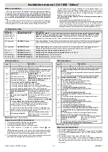
Temp Sensor
(Optional)
Programming
Assistance Button
(Hood Switch
Interrupt)
TACH Threshold: HIGH
TACH Threshold: NORMAL
SIDE VIEW OF MODULE
Data Port
(Optional)
1- BLACK ........................ GROUND (-)
2- PURPLE ........................... TACH (AC)
3- GREY ................. HOOD SWITCH (-)
4- ORANGE ........ BRAKE SWITCH (+)
5- YELLOW ....... PARKING LIGHTS (+)
GREEN
............
5
th
RELAY
PURPLE
.............
STARTER
ORANGE
...
ACCESSORIES
(Heater Blower Motor)
YELLOW
...........
IGNITION
RED
............
+12V (Battery)
RED
..............
12V (Battery)
PUSH-BUTTON
VALET SWITCH
(Optional on
certain models)
INV-200 Connector
Jumpers for second outputs
(Starter, Ignition, Accessories)
15 A Fuse
30 A Fuse
30 A Fuse
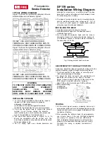
REAR VIEW OF MODULE
WIRING SCHEMATIC
WIRING SCHEMATIC
85
87
(Solenoid Side)
86
30
STARTER WIRE
(Key Side)
IGNITION (+)
N/A
Start Kill Output (-)
87
A
STARTER WIRE
Optional Starter Kill Relay
Optional
programming
port
Optional
programming
port
Starter 2 Jumper
Ignition 2 Jumper
Accessories 2 Jumper
INV-200 CONNECTOR
(Door Lock pulse
inverter)
Data Port
(Optional)
RS-232 Port (ADS)
Temp Sensor
(Optional)
RS232 Port
(ADS)
Shock Sensor
Shock Sensor
2. WHITE/PURPLE ........ (
-
) HORN output
3. BLACK/GREEN ......... (
-
) AUX 2 output
1. GRAY/LIGHT BLUE ... (-) N/A
4. BLACK/BROWN ........ (-) PRIORITY DOOR output
5. YELLOW .................... (
-
) PARKING LIGHTS output
2. WHITE/PURPLE ..... (-) HORN output
3. BLACK/GRENN ...... (-) AUX 2 output
1. GREY/BLUE ............ (-) N/A
4. BLACK/BROWN ..... (-) PRIORITY DOOR
5. YELLOW ................. (-) PARKING LIGHTS
12- YELLOW .......................... (+) Glow plug input
11- GREY ............................... (-) Negative Door input
10- WHITE .............................. (-) GROUND out when running
9- PURPLE ............................ (+) Siren output
8- ORANGE ........................... (-) Hand Brakes input
7- WHITE/ORANGE ............... (-) Starter kill output
6- BLUE/WHITE ..................... (+) Positive Door input
5- WHITE/GREEN .................. (-) DISARM
4- WHITE/BROWN ................. (-) REARM
3- GREEN .............................. (-) UNLOCK
2- BROWN ............................. (-) LOCK
1- BLUE ................................. (-) TRUNK output
LOOP
For Automatic Transmissions
:
Leave Orange wire unconnected.
Loop


